Page 1 of 1
Figure Q2-1 (on the following page) shows a photodiode circuit for measuring small changes in the intensity of infrared
Posted: Mon May 09, 2022 1:31 pm
by answerhappygod
- Figure Q2 1 On The Following Page Shows A Photodiode Circuit For Measuring Small Changes In The Intensity Of Infrared 1 (79.52 KiB) Viewed 29 times
- Figure Q2 1 On The Following Page Shows A Photodiode Circuit For Measuring Small Changes In The Intensity Of Infrared 2 (11.6 KiB) Viewed 29 times
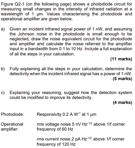
Figure Q2-1 (on the following page) shows a photodiode circuit for measuring small changes in the intensity of infrared radiation at a wavelength of 1 um. Values characterising the photodiode and operational amplifier are given below. a) Given an incident infrared signal power of 1 nW, and assuming the Johnson noise in the photodiode is small enough to be neglected, draw the noise equivalent circuit for the photodiode and amplifier and calculate the noise referred to the amplifier input in a bandwidth from 0.1 to 10 Hz. Include a full explanation of all the steps in your calculation. (11 marks) b) Fully explaining all the steps in your calculation, determine the detectivity when the incident infrared signal has a power of 1 nW. (5 marks) c) Explaining your reasoning, suggest how the detection system could be modified to improve its detectivity. (4 marks) Photodiode: Operational amplifier: Responsivity 0.2 AW at 1 um rms voltage noise 5 nV Hz-12 above 1/f corner frequency of 60 Hz rms current noise 2 PA Hz-1/2 above 1/f corner frequency of 120 Hz
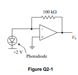
100 kΩ W w V. +2 V Photodiode Figure Q2-1