Page 1 of 1
The runner system for an 8-part mould is shown in Fig. 1. If it is desirable to balance the flow to each of the parts, c
Posted: Mon May 09, 2022 10:03 am
by answerhappygod
- The Runner System For An 8 Part Mould Is Shown In Fig 1 If It Is Desirable To Balance The Flow To Each Of The Parts C 1 (82.19 KiB) Viewed 25 times
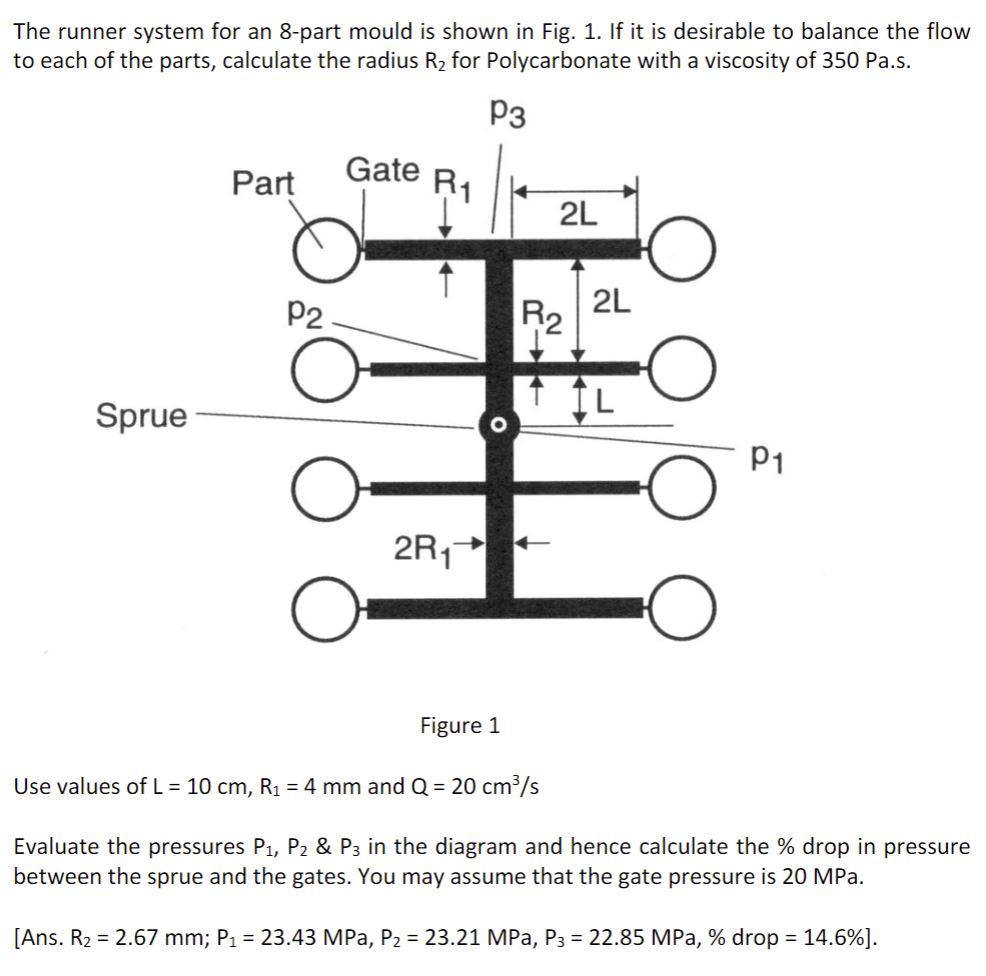
The runner system for an 8-part mould is shown in Fig. 1. If it is desirable to balance the flow to each of the parts, calculate the radius R2 for Polycarbonate with a viscosity of 350 Pa.s. P3 Part Gate RA 2L P2 2L R2 Sprue IL O P1 2R1 Figure 1 Use values of L = 10 cm, R1 = 4 mm and Q = 20 cm/s Evaluate the pressures P1, P2 & P3 in the diagram and hence calculate the % drop in pressure between the sprue and the gates. You may assume that the gate pressure is 20 MPa. [Ans. R2 = 2.67 mm; P1 = 23.43 MPa, P2 = 23.21 MPa, P3 = 22.85 MPa, % drop = 14.6%).