Page 1 of 1
6) Fig. (5.a) shows a schematic diagram of an automobile suspension system. As the car moves along the road, the vertica
Posted: Mon May 09, 2022 9:41 am
by answerhappygod
- 6 Fig 5 A Shows A Schematic Diagram Of An Automobile Suspension System As The Car Moves Along The Road The Vertica 1 (207.19 KiB) Viewed 32 times
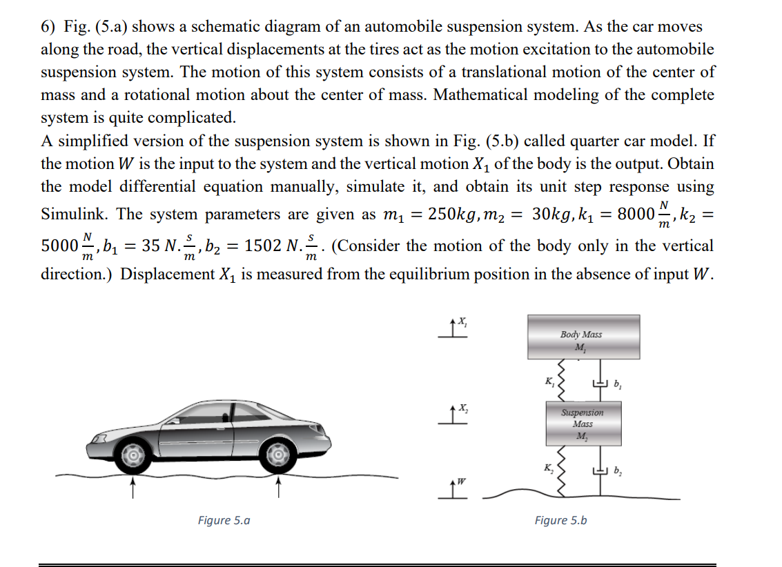
6) Fig. (5.a) shows a schematic diagram of an automobile suspension system. As the car moves along the road, the vertical displacements at the tires act as the motion excitation to the automobile suspension system. The motion of this system consists of a translational motion of the center of mass and a rotational motion about the center of mass. Mathematical modeling of the complete system is quite complicated. A simplified version of the suspension system is shown in Fig. (5.b) called quarter car model. If the motion W is the input to the system and the vertical motion X1 of the body is the output. Obtain the model differential equation manually, simulate it, and obtain its unit step response using Simulink. The system parameters are given as mı = 250kg, m2 30kg, ky = 8000m,k2 5000 m, b2 = 35 n., b2 = 1502 N. (Consider the motion of the body only in the vertical direction.) Displacement X1 is measured from the equilibrium position in the absence of input W. = = = N = т Body Mass M K b, px Suspension Mass M K, b, t” Figure 5.a Figure 5.b