Page 1 of 1
A composite cylindrical wall (shown in Figure QC1) is composed of two materials (A and B) with thermal conductivities ka
Posted: Mon May 09, 2022 9:38 am
by answerhappygod
- A Composite Cylindrical Wall Shown In Figure Qc1 Is Composed Of Two Materials A And B With Thermal Conductivities Ka 1 (346.97 KiB) Viewed 26 times
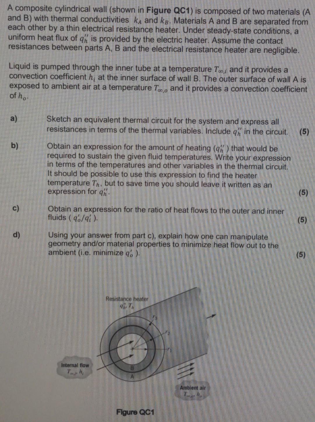
A composite cylindrical wall (shown in Figure QC1) is composed of two materials (A and B) with thermal conductivities ka and kg. Materials A and B are separated from each other by a thin electrical resistance heater. Under steady-state conditions, a uniform heat flux of qh is provided by the electric heater. Assume the contact resistances between parts A, B and the electrical resistance heater are negligible. Liquid is pumped through the inner tube at a temperature Too, and it provides a convection coefficient h; at the inner surface of wall B. The outer surface of wall A is exposed to ambient air at a temperature T.,, and it provides a convection coefficient of ho a) Sketch an equivalent thermal circuit for the system and express all resistances in terms of the thermal variables. Include an in the circuit. (5) b) Obtain an expression for the amount of heating (96) that would be required to sustain the given fluid temperatures. Write your expression in terms of the temperatures and other variables in the thermal circuit. It should be possible to use this expression to find the heater temperature Tr, but to save time you should leave it written as an expression for ch. (5) c) Obtain an expression for the ratio of heat flows to the outer and inner fluids ( 46/48). . (5) d) Using your answer from part c), explain how one can manipulate geometry and/or material properties to minimize heat flow out to the ambient (i.e. minimize 4. ). (5) Resistance heater us Internal flow T. Ambient all Figure QC1