Page 1 of 1
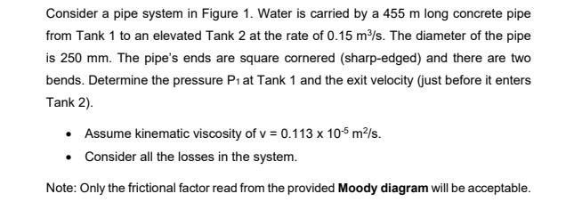
Consider a pipe system in Figure 1. Water is carried by a 455 m long concrete pipe from Tank 1 to an elevated Tank 2 at
Posted: Mon May 09, 2022 9:21 am
by answerhappygod
- Consider A Pipe System In Figure 1 Water Is Carried By A 455 M Long Concrete Pipe From Tank 1 To An Elevated Tank 2 At 1 (27.01 KiB) Viewed 25 times
Consider a pipe system in Figure 1. Water is carried by a 455 m long concrete pipe from Tank 1 to an elevated Tank 2 at the rate of 0.15 m²/s. The diameter of the pipe is 250 mm. The pipe's ends are square cornered (sharp-edged) and there are two bends. Determine the pressure P1 at Tank 1 and the exit velocity (just before it enters Tank 2). • Assume kinematic viscosity of v = 0.113 x 10⁻⁵m²/s. • Consider all the losses in the system. Note: Only the frictional factor read from the provided Moody diagram will be acceptable.