Page 1 of 1
For Further Investigation: Suppose you wanted to set up a limiting circuit that would clip signals above +5.0 V but had
Posted: Mon May 09, 2022 8:22 am
by answerhappygod
- For Further Investigation Suppose You Wanted To Set Up A Limiting Circuit That Would Clip Signals Above 5 0 V But Had 1 (31.42 KiB) Viewed 21 times
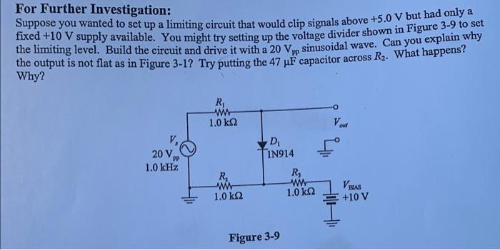
For Further Investigation: Suppose you wanted to set up a limiting circuit that would clip signals above +5.0 V but had only as fixed +10 V supply available. You might try setting up the voltage divider shown in Figure 3.9 to set the limiting level. Build the circuit and drive it with a 20 V, sinusoidal wave. Can you explain why the output is not flat as in Figure 3-12 Try putting the 47 uF capacitor across R2. What happens? Why? PP R W 1.0 KS2 ou 20 V PP 1.0 KHz D 1N914 R ww 1.0 kΩ R ww 1.0 k 2 BAS +10 V Figure 3-9