Page 1 of 1
Objectives line voltage of some transformer may have a plus displacement. Depending upon this phase difference, transfor
Posted: Mon May 09, 2022 8:19 am
by answerhappygod
- Objectives Line Voltage Of Some Transformer May Have A Plus Displacement Depending Upon This Phase Difference Transfor 1 (119.14 KiB) Viewed 24 times
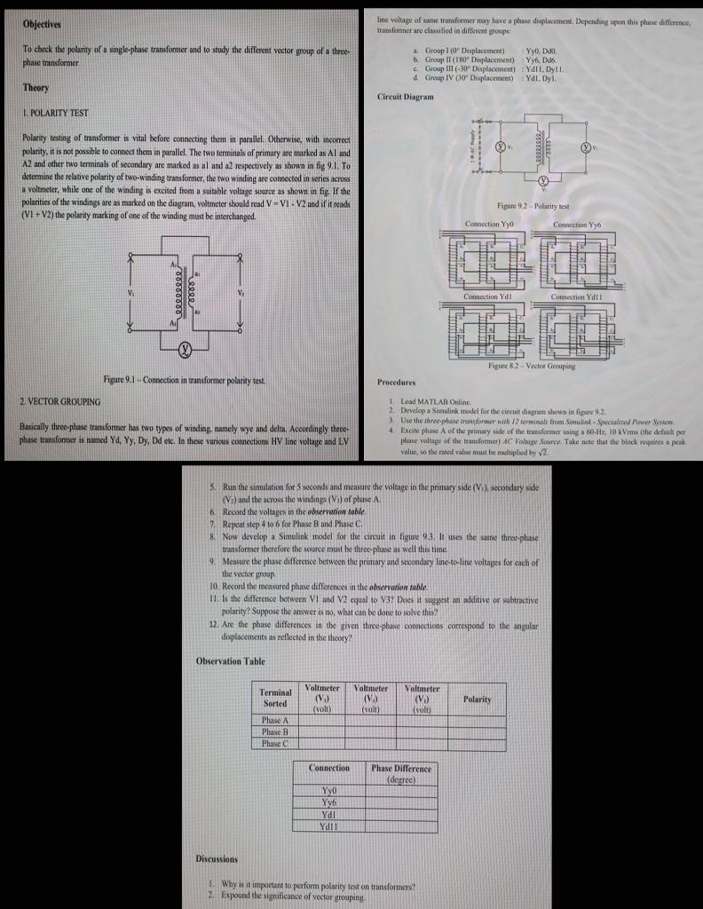
Objectives line voltage of some transformer may have a plus displacement. Depending upon this phase difference, transformer are classified in different groupe To check the polarity of a single-phase transformer and to study the different vector group of a three- phase transformer Group 1 (0 Displacement) Yyo, Dao b. Group IT (180 Deplacement) Yy6.6 c. Group 11-30 Displacement) Ydll. Dyll. 1 Group IV (30 Displacement) YdI, Dyl. Theory Circuit Diagram L. POLARITY TEST Polarity testing of transformer is vital before connecting them in parallel. Otherwise, with incorrect polarity, it is not possible to connect them in parallel. The two terminals of primary are marked as Al and A2 and other two terminals of secondary are marked as al and a2 respectively as shown in fig 9.1. To determine the relative polarity of two-winding transformer, the two winding are connected in series across a voltmeter, while one of the winding is excited from a suitable voltage source as shown in fig. If the polarities of the windings are as marked on the diagram, voltmeter should read V-VI. V2 and if it reads (VI+V2) the polarity marking of one of the winding must be interchanged. Figure 9.2 - Polarity test Connection Yyo Connection Yyo V cececele erre V Connection Yd1 Connection Yd!! A - Figure 82 - Vector Grouping Figure 9.1 - Connection in transformer polarity test Procedures 2. VECTOR GROUPING Basically three-phase transformer has two types of winding, namely wye and delta. Accordingly three phase transformer is named Ya, Yy. Dy, Dd etc. In these various connections HIV line voltage and LIV Load MATLAB Online 2. Develop a Sivalink model for the circuit diagram shown in figure 1.2 3. Use the three transfur with terminals from Somulik. Special Power Sysw. 4. Excite phase of the primary side of the transformer using a co H. 10 kVrms the default per phase voltage of the transformer) AC Voltage Source. Take note that the block requires a pak value, so the rated valur must be multiplied by V2 5. Run the simulation for 5 seconds and measure the voltage in the ponuryside (V), Necondary side (V) and the across the windings (V) of phase A 6. Record the voltages in the observation table 7. Repeat step 4 to 6 for Phase Band Phase C 8 Now develop a Simulink model for the circuit in figure 93. It uses the same three-phase transformer therefore the source must be three-phase as well this time 9. Measure the phase difference between the primary and secondary line-to-line voltages for each of the vector group 10. Record the monsured phase differences in the observation table 11. Is the difference between VI and V2 equal to V3 Does it suggest an additive or subtractive polarity Suppose the answer is no what can be done to solve this: 12. Are the phase differences in the given three-phase connections correspond to the angular displacements is reflected in the theory! Observation Table Voltmeter (VO (volt) Voltmeter (V (valt) Voltmeter () (volt) Polarity Terminal Sorted Phase A A Phase B B Phase C Connection Phase Difference (degree) YO YVE Ydi Ydll Discussions Why is it important to perform polarity test on transformers! 2 Expound the significance of vector grouping