Page 1 of 1
Section A 1. A linear resistive network is shown in Figure 1. Vs 10 V +1 w R1 100 w la R2 50 2 Is 100 mA w R 100Ω R 100Ω
Posted: Mon May 09, 2022 8:16 am
by answerhappygod
- 1 (59.69 KiB) Viewed 19 times
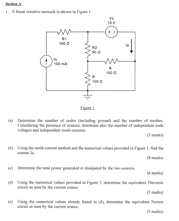
Section A 1. A linear resistive network is shown in Figure 1. Vs 10 V +1 w R1 100 w la R2 50 2 Is 100 mA w R 100Ω R 100Ω Figure 1 (a) Determine the number of nodes (including ground) and the number of meshes. Considering the presence of sources, determine also the number of independent node voltages and independent mesh currents. (3 marks) (b) Using the mesh current method and the numerical values provided in Figure 1, find the current la. (8 marks) (c) Determine the total power generated or dissipated by the two sources. (6 marks) (d) Using the numerical values provided in Figure 1, determine the equivalent Thevenin circuit as seen by the current source. (5 marks) (e) Using the numerical values already found in (d), determine the equivalent Norton circuit as seen by the current source. (3 marks)