Page 1 of 1
Problem 3 Sometimes it is necessary to install special power equipment to purposely redistribute power flows over a para
Posted: Mon May 09, 2022 8:09 am
by answerhappygod
- Problem 3 Sometimes It Is Necessary To Install Special Power Equipment To Purposely Redistribute Power Flows Over A Para 1 (83.02 KiB) Viewed 20 times
- Problem 3 Sometimes It Is Necessary To Install Special Power Equipment To Purposely Redistribute Power Flows Over A Para 2 (38.37 KiB) Viewed 20 times
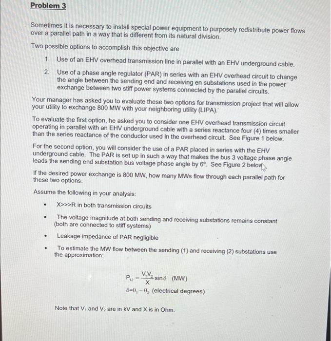
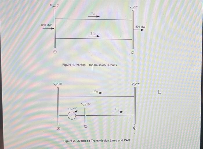
Problem 3 Sometimes it is necessary to install special power equipment to purposely redistribute power flows over a parallel path in a way that is different from its natural division Two possible options to accomplish this objective are 1. Use of an EHV overhead transmission line in parallel with an EHV underground cable. 2. Use of a phase angle regulator (PAR) in series with an EHV overhead circuit to change the angle between the sending end and receiving en substations used in the power exchange between two stiff power systems connected by the parallel circuits. Your manager has asked you to evaluate these two options for transmission project that will allow your utility to exchange 800 MW with your neighboring utility (LIPA). To evaluate the first option, he asked you to consider one EHV overhead transmission circuit operating in parallel with an EHV underground cable with a series reactance four (4) times smaller than the series reactance of the conductor used in the overhead circuit. See Figure 1 below. For the second option, you will consider the use of a PAR placed in series with the EHV underground cable. The PAR is set up in such a way that makes the bus 3 voltage phase angle leads the sending end substation bus voltage phase angle by 6° See Figure 2 belon If the desired power exchange is 800 MW, how many MWs flow through each parallel path for these two options Assume the following in your analysis: X>>>R in both transmission circuits The voltage magnitude at both sending and receiving substations remains constant (both are connected to stiff systems) Leakage impedance of PAR negligible To estimate the MW flow between the sending (1) and receiving (2) substations use the approximation: . . . V.VA P2 sino (MW) х 8=0,-, (electrical degrees) Note that V, and V, are in kV and X is in Ohm.
V,210 V. 22 P 800 MW 800 MW Figure 1. Parallel Transmission Circuits V,210 V.22 میرا V, 216 1: Figure 2. Overhead Transmission Lines and PAR