Page 1 of 1
A BJT can be configured in three ways depending on which terminal is used as a common terminal. The three basic single-s
Posted: Mon May 09, 2022 7:59 am
by answerhappygod
- A Bjt Can Be Configured In Three Ways Depending On Which Terminal Is Used As A Common Terminal The Three Basic Single S 1 (29.17 KiB) Viewed 24 times

- A Bjt Can Be Configured In Three Ways Depending On Which Terminal Is Used As A Common Terminal The Three Basic Single S 2 (25.63 KiB) Viewed 24 times
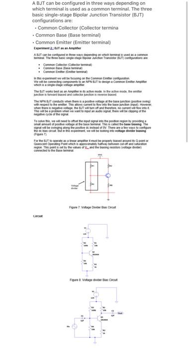
A BJT can be configured in three ways depending on which terminal is used as a common terminal. The three basic single-stage Bipolar Junction Transistor (BJT) configurations are: . Common Collector (Collector termina Common Base (Base terminal) Common Emitter (Emitter terminal) Experiment 2T Amplifier A BIT can be configured in the ways depending on which terms as a common terminal The Three basic single stage par Scho Transit (BIT) configurations are Common Comedor Chirimin Common Beer Common Emmertiminal In this experiment we will be focusing on the Common Emter configuration We wil becomecting components to NPN BUT o Onsign a Common Ente Angie which is a singloon voltage amplifier unction sed and collections The Two best teach modelo do the The Nutches pour voit the lection with respect to the critet Thaws current to fio to the base onction roul Howeve when the pede votapete BUT Wum off and therefore, no current we soweto This will be a problem wione want to not an audios there will be dipping of the negative cycle of the To solve the we need to offer the input igra to the position region by providing a moltout all positive apo u be base on the called a tarte betinge sind be swinging along the positive de instead of ov. There are a few way to configure de bus arcu ut periment will be looking to voltage divisering For me to perfettamente por porter Guiescent Operating Point which promately they be cut off and saturation connected by the Basteira region. This point is set by the values of Ind the big resistors voilage dividen 9 To Vote bilder Crot Court Figure Votage de Cast 3 1 . 11 E
Procedures: (a) Connect the circuit in Figure 8. Measure the point and record the use and Le () Calculate and record the bias voltage V. (c) Calculate the current L. Note that when the BJT is in saturation. V. - OV (0) Next, connect 2 additional capacitors to the common and base terminats as per () input a 1 kHz sinusoidal signal with amplitude of 200mVp from the function generator in Observe the input and output signals and record these peaks valors. Figure 9 Observations & Results 1 O-point measurement Calculated value Measured value V Calculate the values of one and a (Show your workings below 2 Calculate the value of Bias voltage, V. (Show your workingsbestow 3 Calculate the collector saturation current L. Assume V = OV for BJT in saturation (Show your worlongs below) 4. Capture a screenshot of the signal at the base of the transistor, Indicate the blas Voltage 5. Capture a screenshot of the signal at the output (at the common terminal) Indicate the amplitude of the output signal when x = 200mV.