Page 1 of 1
(b) Figure 7 shows a logic circuit with two inputs A and B and one NAND gate, one Ex-OR gate and one Ex-NOR gate. (i) Wr
Posted: Mon May 09, 2022 7:58 am
by answerhappygod
- B Figure 7 Shows A Logic Circuit With Two Inputs A And B And One Nand Gate One Ex Or Gate And One Ex Nor Gate I Wr 1 (123.19 KiB) Viewed 27 times
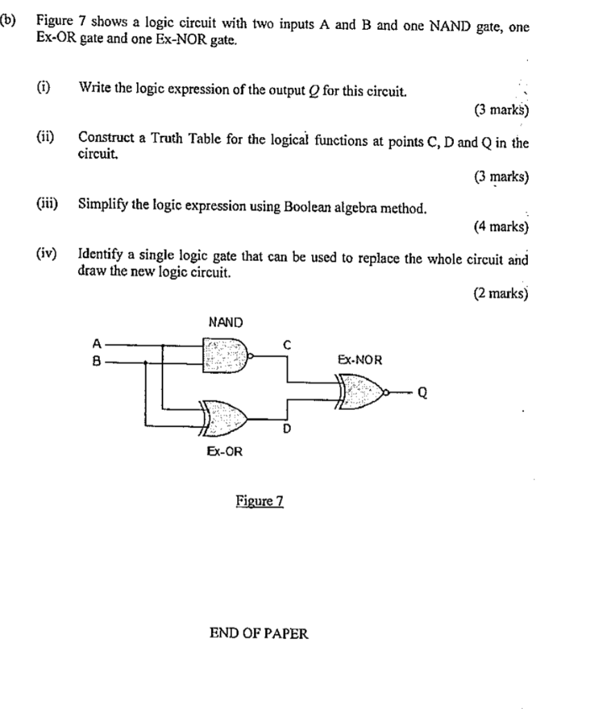
(b) Figure 7 shows a logic circuit with two inputs A and B and one NAND gate, one Ex-OR gate and one Ex-NOR gate. (i) Write the logic expression of the output for this circuit. (3 marks) (ii) Construct a Truth Table for the logical functions at points C, D and Q in the circuit. (3 marks) (iii) Simplify the logic expression using Boolean algebra method. (4 marks) (iv) Identify a single logic gate that can be used to replace the whole circuit and draw the new logic circuit. (2 marks) NAND с A B Ex-NOR Q Ex-OR Figure 7 END OF PAPER