Page 1 of 1
4(a) The op-amp circuit shown in Figure 5 is used as an active filter with the following component values: R = Rz=10 k 2
Posted: Mon May 09, 2022 7:58 am
by answerhappygod
- 4 A The Op Amp Circuit Shown In Figure 5 Is Used As An Active Filter With The Following Component Values R Rz 10 K 2 1 (147.47 KiB) Viewed 28 times
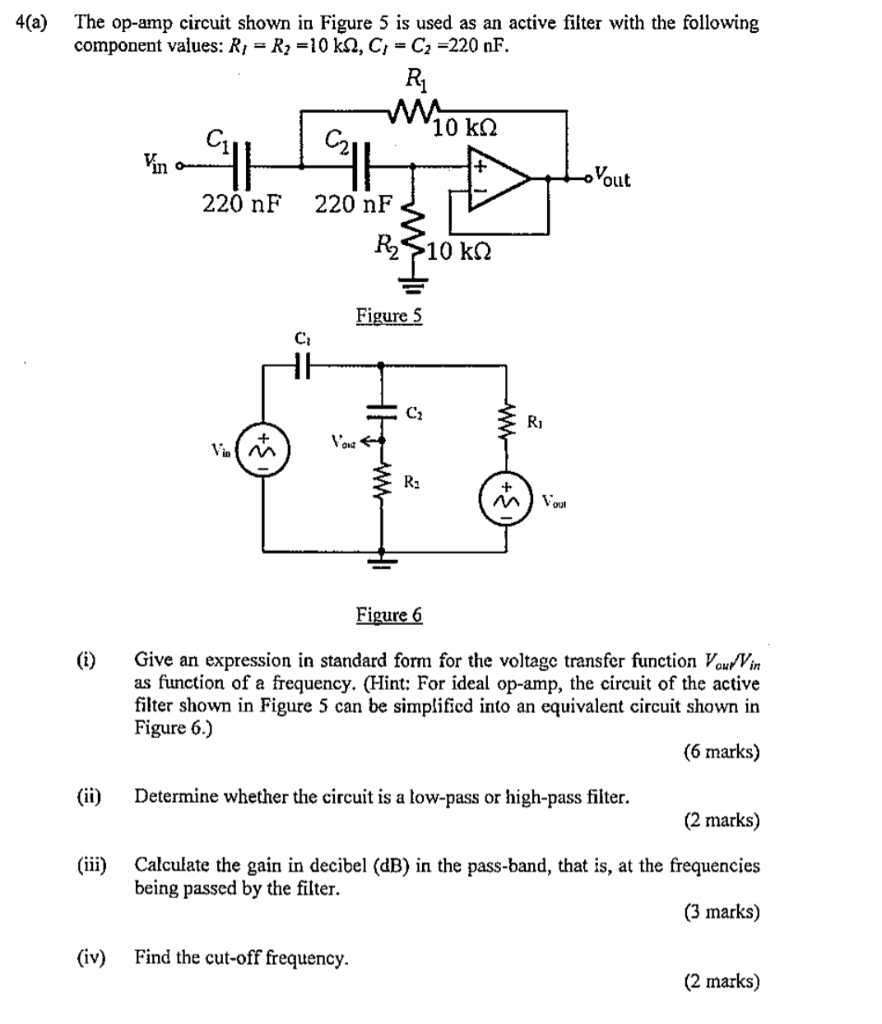
4(a) The op-amp circuit shown in Figure 5 is used as an active filter with the following component values: R = Rz=10 k 2, C, = C2 =220 nF. Ri m 10 k 2 C2, Vin Yout 220 nF 220 nF R->10 kΩ Figure 5 C: C2 Ri Volg R. w Voul Figure 6 Give an expression in standard form for the voltage transfer function Vouwin as function of a frequency. (Hint: For ideal op-amp, the circuit of the active filter shown in Figure 5 can be simplificd into an equivalent circuit shown in Figure 6.) (6 marks) ( (ii) Determine whether the circuit is a low-pass or high-pass filter. (2 marks) (iii) Calculate the gain in decibel (dB) in the pass-band, that is, at the frequencies being passed by the filter. (3 marks) (iv) Find the cut-off frequency. (2 marks)