Page 1 of 1
Q.4 You are developing a set of continuity test for the 74LM138 device in Final Test. The following datalog (Fig. Q4a) i
Posted: Mon May 09, 2022 7:44 am
by answerhappygod
- Q 4 You Are Developing A Set Of Continuity Test For The 74lm138 Device In Final Test The Following Datalog Fig Q4a I 1 (311.37 KiB) Viewed 24 times
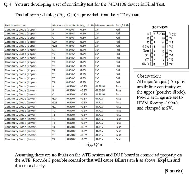
Q.4 You are developing a set of continuity test for the 74LM138 device in Final Test. The following datalog (Fig. Q4a) is provided from the ATE system: (TOP VIEW Agi 16VCc B2 15 YO co 1441 G2A04 13 Y2 G25 12. Y3 G16 11D Y4 Yid 10 Y5 GND (e 2016 Test item Name: Continuity Diode (Upper) Continuity Diode (Upper) Continuity Diode (Upper) Continuity Diode (Upper) Continuity Diode (Upper) Continuity Diode (Upper) Continuity Diode (Upper) Continuity Diode (Upper) Continuity Diode (Upper) Continuity Diode (Upper) Continuity Diode (Upper) Continuity Diode (Upper) Continuity Diode (Upper) Continuity Diode (Upper) Continuity Diode (Lower) Continuity Diode (Lower) Continuity Diode (Lower) Continuity Diode (Lower) Continuity Diode (Lower) Continuity Diode (Lower) Continuity Diode (Lower) Continuity Diode Lower) Continuity Diode (Lower) Continuity Diode Lower) Continuity Diode (Lower) Continuity Diode (Lower) Continuity Diode (Lower) Continuity Diode (Lower) Pin name: Low Limit: High Limit: Measurement: Pass / Fail: А 0.450V 0.8V 2v Fail B 0.450V 0.8V 2V Fail C 0.450V 0.8V 2v Fail G2A 0.450V 0.8V 27 Fail G2B 0.450V 0.8V 2v Fail G1 0.450V 0.8V 2V Fail YO 0.450V 0.8V 12V Fail Y1 0.450V 0.8V 2V Fail Y2 0.450V 0.8V 2v Fail Y3 0.450V 0.8V 2V Fail Y4 0.450V 0.8V 2V Fail YS 0.450V 0.8V 2v Fail Y6 0.450V 0.8V 2V Fail Y7 0.450V 0.8V 2V Fail A -0.500V -0.8V -0.631V Pass B -0.500V -0.8V -0.632V Pass с -0.500V -0.631V Pass G2A -0.500V -0.8V -0.711 Pass G2B -0.500V -0.8V -0.71V Pass G1 -0.SOOV -0.8V -0.71V Pass YO -0.500V -0.8V -0.71V Pass Y1 -0.500V -0.8V -0.717 Pass Y2 -0.500V -0.8V -0.71V Pass Y3 -0.500V -0.8V -0.71V Pass -0.500V -0.8V -0.71V -0.500V -0.8V -0.717 Pass -0.500V -0.8V -0.71V Pass Y7 -0.500V -0.8V -0.717 Pass Observation: All input/output (i/o) pins are failing continuity on the upper (positive diode). PPMU settings are set to IFVM forcing -100A and clamped at 2V. -0.8V Pass 5531 Fig. Q4a Assuming there are no faults on the ATE system and DUT board is connected properly on the ATE. Provide 3 possible scenarios that will cause failures such as above. Explain and illustrate clearly [9 marks]