Page 1 of 1
2. A resistive load (RL) is driven by a circuit comprising a sinusoidal voltage source (vs), a resistor (R), an inductor
Posted: Mon May 09, 2022 7:42 am
by answerhappygod
- 2 A Resistive Load Rl Is Driven By A Circuit Comprising A Sinusoidal Voltage Source Vs A Resistor R An Inductor 1 (93.13 KiB) Viewed 28 times
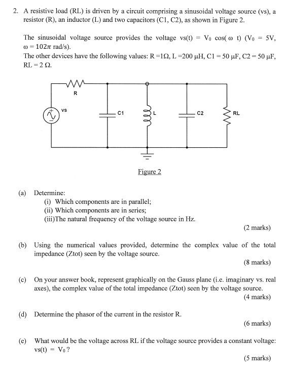
2. A resistive load (RL) is driven by a circuit comprising a sinusoidal voltage source (vs), a resistor (R), an inductor (L) and two capacitors (C1, C2), as shown in Figure 2. The sinusoidal voltage source provides the voltage vs(t) = Vo cos(at) (V. 5V, m = 1027 rad/s). The other devices have the following values: R=122, L =200 uH, C1 = 50 uF, C2 = 50 uF, RL = 20 w R W VS C1 C2 RL ell Figure 2 (a) Determine: (1) Which components are in parallel; (ii) Which components are in series; (iii) The natural frequency of the voltage source in Hz. (2 marks) (b) Using the numerical values provided, determine the complex value of the total impedance (Ztot) seen by the voltage source. (8 marks) (c) On your answer book, represent graphically on the Gauss plane (i.e. imaginary vs. real axes), the complex value of the total impedance (Ztot) seen by the voltage source. (4 marks) (d) Determine the phasor of the current in the resistor R. (6 marks) (e) What would be the voltage across RL if the voltage source provides a constant voltage: vs(t) = Vo? (5 marks)