Page 1 of 1
= 3. With reference to the circuit in Figure 3, assume the following (phasors) values for AC analysis: • Vin = 173.2 20°
Posted: Mon May 09, 2022 7:42 am
by answerhappygod
- 3 With Reference To The Circuit In Figure 3 Assume The Following Phasors Values For Ac Analysis Vin 173 2 20 1 (72.17 KiB) Viewed 26 times
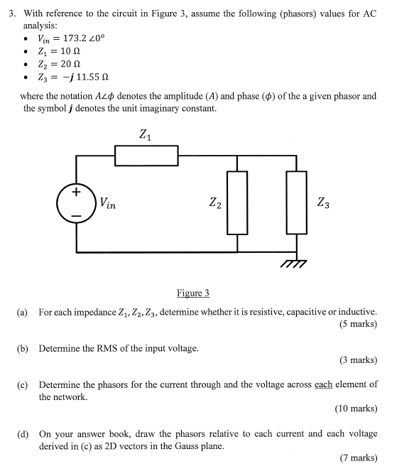
= 3. With reference to the circuit in Figure 3, assume the following (phasors) values for AC analysis: • Vin = 173.2 20° • Z1 = 10 12 • Z2 = 20 Ω • 23 = -j 11.55 where the notation A2D denotes the amplitude (A) and phase (™) of the a given phasor and the symbol j denotes the unit imaginary constant. Z + Vin N Z2 Z3 Figure 3 (a) For each impedance 21,22,23, determine whether it is resistive, capacitive or inductive. (5 marks) (b) Determine the RMS of the input voltage. (3 marks) (c) Determine the phasors for the current through and the voltage across each element of the network. (10 marks) (d) On your answer book, draw the phasors relative to each current and each voltage derived in (c) as 2D vectors in the Gauss plane. (7 marks)