Page 1 of 1
For the circuit given in Fig. QB2, Vcc = 15V, Rs = 100, R1 = 50 k92, Rc = 30012, Rbe = 100 12, and gm = 0.5S. i. Describ
Posted: Mon May 09, 2022 7:40 am
by answerhappygod
- For The Circuit Given In Fig Qb2 Vcc 15v Rs 100 R1 50 K92 Rc 30012 Rbe 100 12 And Gm 0 5s I Describ 1 (82.28 KiB) Viewed 22 times
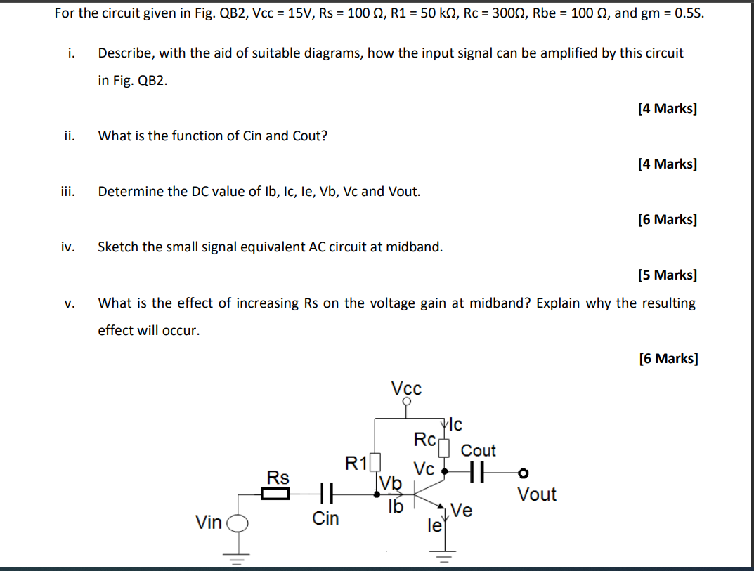
For the circuit given in Fig. QB2, Vcc = 15V, Rs = 100, R1 = 50 k92, Rc = 30012, Rbe = 100 12, and gm = 0.5S. i. Describe, with the aid of suitable diagrams, how the input signal can be amplified by this circuit in Fig. QB2. [4 Marks] ii. What is the function of Cin and Cout? [4 Marks] iii. iv. Determine the DC value of Ib, Ic, le, Vb, Vc and Vout. [6 Marks) Sketch the small signal equivalent AC circuit at midband. [5 Marks] What is the effect of increasing Rs on the voltage gain at midband? Explain why the resulting V. effect will occur. [6 Marks] Vcc 0 vic RC Cout Rs R10 Vc HE Vb HE lb Cin Ve le o Vout Vin HO