Page 1 of 1
In the circuit shown in the figure (Figure 1), the capacitor has capacitance C=20 μF and is initially charged to 100 V w
Posted: Fri May 06, 2022 10:36 am
by answerhappygod
- 1 (158.39 KiB) Viewed 40 times
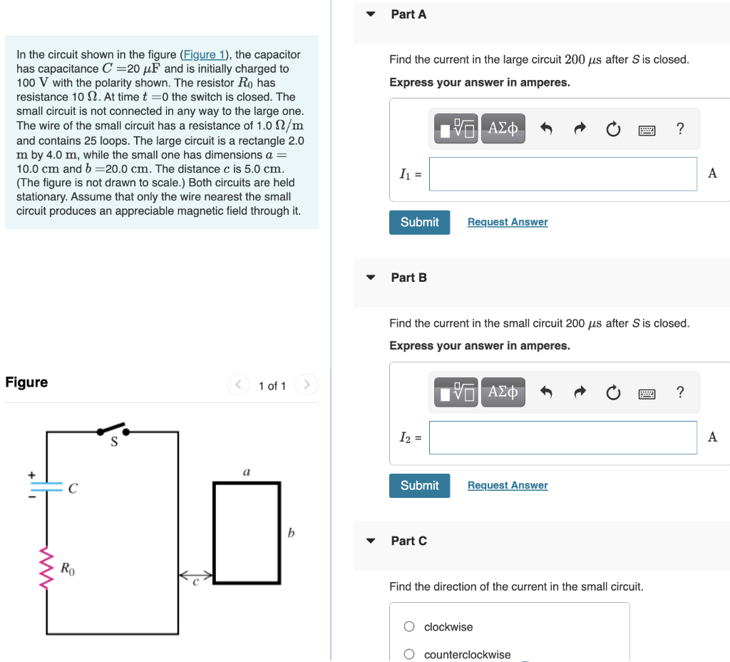
In the circuit shown in the figure (Figure 1), the capacitor has capacitance C=20 μF and is initially charged to 100 V with the polarity shown. The resistor Ro has resistance 102. At time t=0 the switch is closed. The small circuit is not connected in any way to the large one. The wire of the small circuit has a resistance of 1.0 N/m and contains 25 loops. The large circuit is a rectangle 2.0 m by 4.0 m, while the small one has dimensions a = 10.0 cm and b=20.0 cm. The distance c is 5.0 cm. (The figure is not drawn to scale.) Both circuits are held stationary. Assume that only the wire nearest the small circuit produces an appreciable magnetic field through it. Figure 1 of 1 Ro S a Part A Find the current in the large circuit 200 μs after S is closed. Express your answer in amperes. 17 ΑΣΦ ? I₁ = Submit A Request Answer Part B Find the current in the small circuit 200 us after S is closed. Express your answer in amperes. —| ΑΣΦ ? I₂ = Submit Request Answer Part C Find the direction of the current in the small circuit. O clockwise O counterclockwise A