Page 1 of 1
Question 3 a) Figure Q3(a) shows a rigid L-shaped beam 'ABCDE'. The beam is pinned at 'B' and simply supported at 'C'. T
Posted: Fri May 06, 2022 6:40 am
by answerhappygod
- Question 3 A Figure Q3 A Shows A Rigid L Shaped Beam Abcde The Beam Is Pinned At B And Simply Supported At C T 1 (93.65 KiB) Viewed 32 times
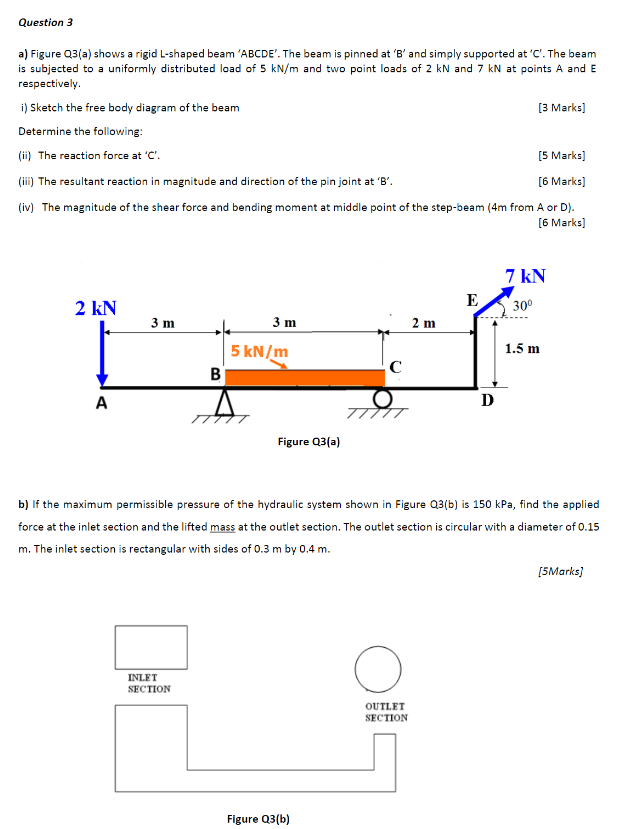
Question 3 a) Figure Q3(a) shows a rigid L-shaped beam 'ABCDE'. The beam is pinned at 'B' and simply supported at 'C'. The beam is subjected to a uniformly distributed load of 5 kN/m and two point loads of 2 kN and 7 kN at points A and E respectively. i) Sketch the free body diagram of the beam [3 Marks] Determine the following: (ii) The reaction force at 'C'. [5 Marks] (iii) The resultant reaction in magnitude and direction of the pin joint at 'B'. [6 Marks] (iv) The magnitude of the shear force and bending moment at middle point of the step-beam (4m from A or D). [6 Marks] 7 kN E 2 kN 30⁰ 3 m 3 m 2 m 1.5 m с B A D A 유유 TTTTT Figure Q3(a) b) If the maximum permissible pressure of the hydraulic system shown in Figure Q3(b) is 150 kPa, find the applied force at the inlet section and the lifted mass at the outlet section. The outlet section is circular with a diameter of 0.15 m. The inlet section is rectangular with sides of 0.3 m by 0.4 m. [5Marks] INLET SECTION OUTLET SECTION 5 kN/m Figure Q3(b)