Page 1 of 1
The figure shows the cam-spring system that is supported by two bearings. Axial load effects are taken by right end bear
Posted: Thu May 05, 2022 6:21 pm
by answerhappygod
- The Figure Shows The Cam Spring System That Is Supported By Two Bearings Axial Load Effects Are Taken By Right End Bear 1 (53.95 KiB) Viewed 24 times
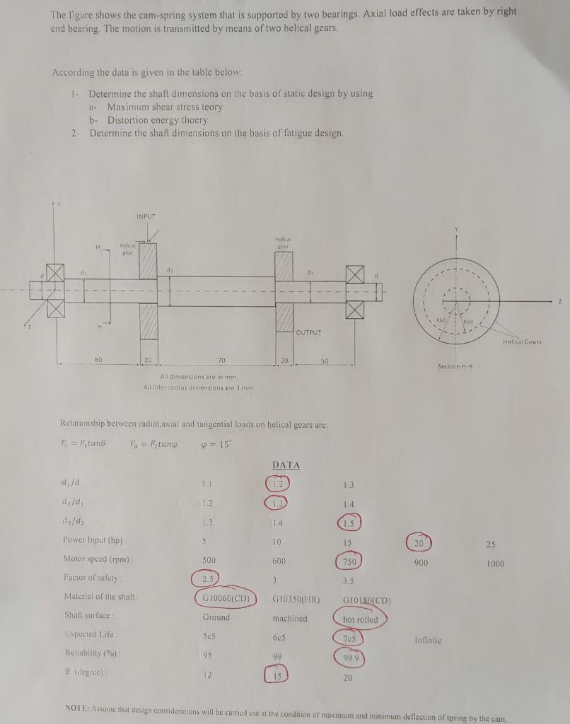
The figure shows the cam-spring system that is supported by two bearings. Axial load effects are taken by right end bearing. The motion is transmitted by means of two helical gears. According the data is given in the table below: 1- Determine the shaft dimensions on the basis of static design by using a- Maximum shear stress teory b- Distortion energy thoery 2- Determine the shaft dimensions on the basis of fatigue design. INPUT helical H Helical grat par di di +1 LPG AGO, 150 OUTPUT 60 20 70 20 50 Section H.H All dimensions are in tim, All fillet radius dimensions are 3 mm. Relationship between radial.axial and tangential loads on helical gears are: F = F,tano F = F,tanp = 15' d₁/d 1.3 1,2 1.4 dy/d, 1.3 1.5 Power Input (hp): 5 15 20 Motor speed (rpm): 500 750 900 Factor of safety: 2,5 3.5 Material of the shaft: G10060(CD) Shall surface Ground Expected Life: 505 Infinite Reliability (%): 95 0 (degree): 12 15 NOTE: Assume that design considerations will be carried out at the condition of maximum and minimum deflection of spring by the cam. 100 DATA 1.2 1.4 10 600 3 G10350(HR) machined 605 99 1000. GIOL80(CD) hot rolled 99.9 Helical Gears 25 1000 2