Page 1 of 1
A crank-slider mechanism is shown in Figure 1. Perform kinetostatic analysis for the mechanism. The crank is running at
Posted: Thu May 05, 2022 6:11 pm
by answerhappygod
- A Crank Slider Mechanism Is Shown In Figure 1 Perform Kinetostatic Analysis For The Mechanism The Crank Is Running At 1 (118.43 KiB) Viewed 34 times
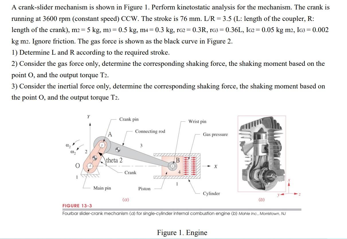
A crank-slider mechanism is shown in Figure 1. Perform kinetostatic analysis for the mechanism. The crank is running at 3600 rpm (constant speed) CCW. The stroke is 76 mm. L/R = 3.5 (L: length of the coupler, R: length of the crank), m2 = 5 kg, m3 = ( 0.5 kg, m4 = 0.3 kg, rG2 = 0.3R, rG3 = 0.36L, IG2 = 0.05 kg m2, IG3 = 0.002 kg m2. Ignore friction. The gas force is shown as the black curve in Figure 2. 1) Determine L and R according to the required stroke. 2) Consider the gas force only, determine the corresponding shaking force, the shaking moment based on the point O, and the output torque T2. 3) Consider the inertial force only, determine the corresponding shaking force, the shaking moment based on the point O, and the output torque T2. Y Crank pin Wrist pin Connecting rod Gas pressure → theta 2 -X 4 1 Main pin Piston Cylinder (a) (b) FIGURE 13-3 Fourbar slider-crank mechanism (a) for single-cylinder internal combustion engine (b) Mahle Inc., Morristown, NJ Figure 1. Engine @₂ Crank B
15 KN 13 KN 0 Gas Force KN 650 710 0 180 360 540 Gas-Force vs Crank Angle Figure 2. Gas Force 10 160 13 KN 2 kN 720