Page 1 of 1
(Sampling of signals) The system illustrated in Figure 1 is utilized to sample a continuous-time signal r(t) with a samp
Posted: Thu May 05, 2022 3:14 pm
by answerhappygod
- Sampling Of Signals The System Illustrated In Figure 1 Is Utilized To Sample A Continuous Time Signal R T With A Samp 1 (111.35 KiB) Viewed 19 times
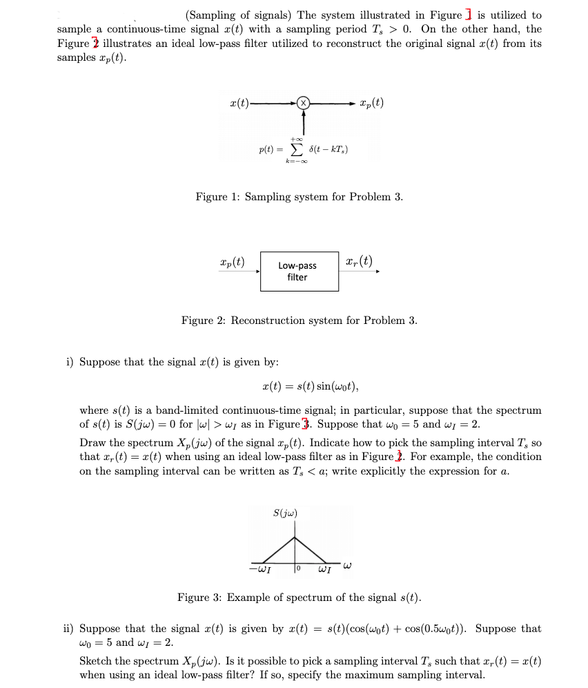
(Sampling of signals) The system illustrated in Figure 1 is utilized to sample a continuous-time signal r(t) with a sampling period T, > 0. On the other hand, the Figure 2 illustrates an ideal low-pass filter utilized to reconstruct the original signal r(t) from its samples xp(t). x(t)- xp (t) +∞o p(t)= (tkT₂) k=-∞0 Figure 1: Sampling system for Problem 3. xp(t) Low-pass x, (t) filter Figure 2: Reconstruction system for Problem 3. i) Suppose that the signal r(t) is given by: x(t) = s(t) sin(wot), where s(t) is a band-limited continuous-time signal; in particular, suppose that the spectrum of s(t) is S(jw) = 0 for w|wy as in Figure 3. Suppose that wo = 5 and wy = 2. Draw the spectrum Xp(jw) of the signal xp(t). Indicate how to pick the sampling interval T, so that , (t) = x(t) when using an ideal low-pass filter as in Figure 2. For example, the condition on the sampling interval can be written as T, <a; write explicitly the expression for a. S(jw) W WI Figure 3: Example of spectrum of the signal s(t). ii) Suppose that the signal r(t) is given by r(t) = s(t) (cos(wot) + cos(0.5wot)). Suppose that wo = 5 and wy = 2. Sketch the spectrum Xp(jw). Is it possible to pick a sampling interval T, such that x, (t) = x(t) when using an ideal low-pass filter? If so, specify the maximum sampling interval. اليا-