Page 1 of 1
Q1. (a) Figure 1 shows the internal circuitry for a charger prototype. You, the development engineer, are required to do
Posted: Thu May 05, 2022 3:03 pm
by answerhappygod
- Q1 A Figure 1 Shows The Internal Circuitry For A Charger Prototype You The Development Engineer Are Required To Do 1 (55.97 KiB) Viewed 33 times
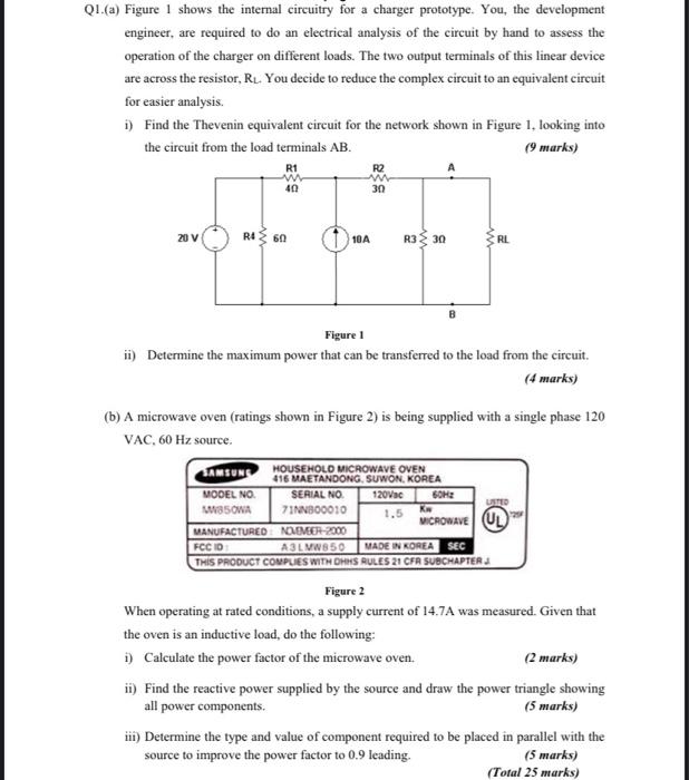
Q1. (a) Figure 1 shows the internal circuitry for a charger prototype. You, the development engineer, are required to do an electrical analysis of the circuit by hand to assess the operation of the charger on different loads. The two output terminals of this linear device are across the resistor, R₁. You decide to reduce the complex circuit to an equivalent circuit for easier analysis. i) Find the Thevenin equivalent circuit for the network shown in Figure 1, looking into the circuit from the load terminals AB. (9 marks) R1 www 40 R2 www 30 20 V R4 60 R3 30 Figure 1 ii) Determine the maximum power that can be transferred to the load from the circuit. (4 marks) (b) A microwave oven (ratings shown in Figure 2) is being supplied with a single phase 120 VAC, 60 Hz source. HOUSEHOLD MICROWAVE OVEN 416 MAETANDONG, SUWON, KOREA SAMSUNG MODEL NO. MWB50WA 120Vac 60Hz SERIAL NO. 71NN800010 LISTED Kw 1.5 MICROWAVE U NOVEMBER-2000 MANUFACTURED FCC ID A3LMW850 MADE IN KOREA SEC THIS PRODUCT COMPLIES WITH OHHS RULES 21 CFR SUBCHAPTERJ Figure 2 When operating at rated conditions, a supply current of 14.7A was measured. Given that the oven is an inductive load, do the following: i) Calculate the power factor of the microwave oven. (2 marks) ii) Find the reactive power supplied by the source and draw the power triangle showing all power components. (5 marks) iii) Determine the type and value of component required to be placed in parallel with the source to improve the power factor to 0.9 leading. (5 marks) (Total 25 marks) 10A ww RL