Page 1 of 1
Q1.(a) Figure 1 shows the internal circuitry for a charger prototype. You, the development engineer, are required to do
Posted: Thu May 05, 2022 3:03 pm
by answerhappygod
- Q1 A Figure 1 Shows The Internal Circuitry For A Charger Prototype You The Development Engineer Are Required To Do 1 (104.32 KiB) Viewed 39 times
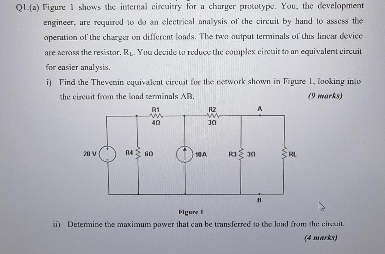
Q1.(a) Figure 1 shows the internal circuitry for a charger prototype. You, the development engineer, are required to do an electrical analysis of the circuit by hand to assess the operation of the charger on different loads. The two output terminals of this linear device are across the resistor, RL. You decide to reduce the complex circuit to an equivalent circuit for easier analysis. i) Find the Thevenin equivalent circuit for the network shown in Figure 1, looking into the circuit from the load terminals AB. (9 marks) A R1 www 40 R2 ww ვი R4 ≥ 60 20 V RL B Figure 1 ii) Determine the maximum power that can be transferred to the load from the circuit. (4 marks) 10A R330