Page 1 of 1
4. The equivalent circuit for the bipolar transistor in Fig.4 has components: r₂ = 300 [2], C₁= 13.2 [pF], C₁= 0.4 [pF],
Posted: Thu May 05, 2022 2:44 pm
by answerhappygod
- 4 The Equivalent Circuit For The Bipolar Transistor In Fig 4 Has Components R 300 2 C 13 2 Pf C 0 4 Pf 1 (113.28 KiB) Viewed 39 times
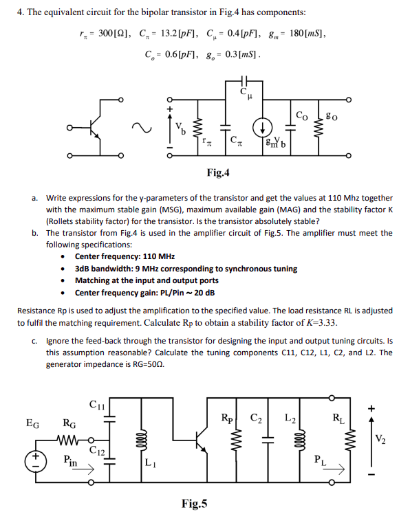
4. The equivalent circuit for the bipolar transistor in Fig.4 has components: r₂ = 300 [2], C₁= 13.2 [pF], C₁= 0.4 [pF], 8- 180 [ms], C= 0.6[pF], 80= 0.3 [ms]. Co 80 I~NH Сп Bm b Fig.4 a. Write expressions for the y-parameters of the transistor and get the values at 110 Mhz together with the maximum stable gain (MSG), maximum available gain (MAG) and the stability factor K (Rollets stability factor) for the transistor. Is the transistor absolutely stable? b. The transistor from Fig.4 is used in the amplifier circuit of Fig.5. The amplifier must meet the following specifications: Center frequency: 110 MHz • 3dB bandwidth: 9 MHz corresponding to synchronous tuning • Matching at the input and output ports Center frequency gain: PL/Pin ~ 20 dB Resistance Rp is used to adjust the amplification to the specified value. The load resistance RL is adjusted to fulfil the matching requirement. Calculate Rp to obtain a stability factor of K-3.33. c. Ignore the feed-back through the transistor for designing the input and output tuning circuits. Is this assumption reasonable? Calculate the tuning components C11, C12, L1, C2, and L2. The generator impedance is RG-500. C11 Rp C₂ L2 RL EG RG SILMIIN ww C12 PL Pin Fig.5 V₂