Page 1 of 1
B {R Figure 1 A parallel plate capacitor with the plate surface area S is placed in a jet of conductive liquid, and magn
Posted: Thu May 05, 2022 2:17 pm
by answerhappygod
- B R Figure 1 A Parallel Plate Capacitor With The Plate Surface Area S Is Placed In A Jet Of Conductive Liquid And Magn 1 (62.74 KiB) Viewed 38 times
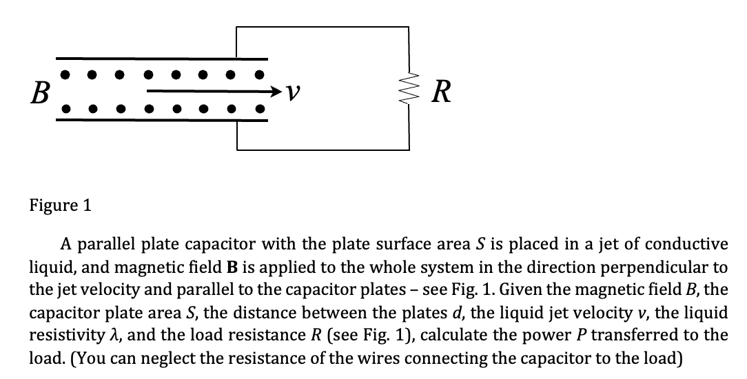
B {R Figure 1 A parallel plate capacitor with the plate surface area S is placed in a jet of conductive liquid, and magnetic field B is applied to the whole system in the direction perpendicular to the jet velocity and parallel to the capacitor plates - see Fig. 1. Given the magnetic field B, the capacitor plate area S, the distance between the plates d, the liquid jet velocity v, the liquid resistivity λ, and the load resistance R (see Fig. 1), calculate the power P transferred to the load. (You can neglect the resistance of the wires connecting the capacitor to the load)