Page 1 of 1
The roof framing plan of a building in Berkeley is shown in the drawing. The girder supports self-weight plus concentrat
Posted: Thu May 05, 2022 12:02 pm
by answerhappygod
- The Roof Framing Plan Of A Building In Berkeley Is Shown In The Drawing The Girder Supports Self Weight Plus Concentrat 1 (149.13 KiB) Viewed 39 times
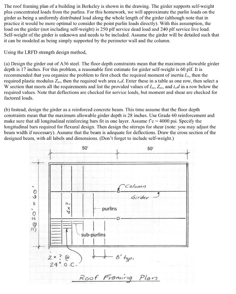
The roof framing plan of a building in Berkeley is shown in the drawing. The girder supports self-weight plus concentrated loads from the purlins. For this homework, we will approximate the purlin loads on the girder as being a uniformly distributed load along the whole length of the girder (although note that in practice it would be more optimal to consider the point purlin loads directly). With this assumption, the load on the girder (not including self-weight) is 250 plf service dead load and 240 plf service live load. Self-weight of the girder is unknown and needs to be included. Assume the girder will be detailed such that it can be modeled as being simply supported by the perimeter wall and the column. Using the LRFD strength design method, (a) Design the girder out of A36 steel. The floor depth constraints mean that the maximum allowable girder depth is 17 inches. For this problem, a reasonable first estimate for girder self-weight is 60 plf. It is recommended that you organize the problem to first check the required moment of inertia Ixx, then the required plastic modulus Zxx, then the required web area tud. Enter these in a table as one row, then select a W section that meets all the requirements and list the provided values of Ixx, Zxx, and twd in a row below the required values. Note that deflections are checked for service loads, but moment and shear are checked for factored loads. (b) Instead, design the girder as a reinforced concrete beam. This time assume that the floor depth constraints mean that the maximum allowable girder depth is 28 inches. Use Grade 60 reinforcement and make sure that all longitudinal reinforcing bars fit in one layer. Assume f'c = 4000 psi. Specify the longitudinal bars required for flexural design. Then design the stirrups for shear (note: you may adjust the beam width if necessary). Assume that the beam adequate for deflections. Draw the cro: section of the designed beam, with all labels and dimensions. (Don't forget to include self-weight.) 50' 50' Column 3@ 20' = 60' 2x? @ 24" 0.C. purlins 0 Girder sub-purlins H 8' typ. Roof Framing Plan