Page 1 of 1
The purpose of the final project is to design various structural members of a two-story steel building 7 bays long by 4
Posted: Thu May 05, 2022 11:48 am
by answerhappygod
- The Purpose Of The Final Project Is To Design Various Structural Members Of A Two Story Steel Building 7 Bays Long By 4 1 (48.74 KiB) Viewed 36 times
- The Purpose Of The Final Project Is To Design Various Structural Members Of A Two Story Steel Building 7 Bays Long By 4 2 (39.11 KiB) Viewed 36 times
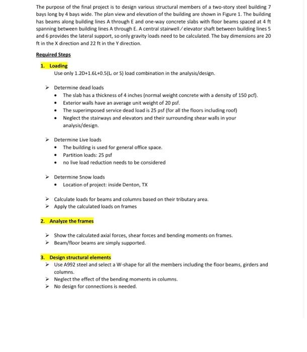
The purpose of the final project is to design various structural members of a two-story steel building 7 bays long by 4 bays wide. The plan view and elevation of the building are shown in Figure 1. The building has beams along building lines A through E and one-way concrete slabs with floor beams spaced at 4 ft spanning between building lines A through E. A central stairwell/elevator shaft between building lines 5 and 6 provides the lateral support, so only gravity loads need to be calculated. The bay dimensions are 20 ft in the X direction and 22 ft in the y direction. Required Steps 1. Loading Use only 1.2D+1.6L+0.5(L, or S) load combination in the analysis/design. > Determine dead loads • The slab has a thickness of 4 inches (normal weight concrete with a density of 150 pcf). Exterior walls have an average unit weight of 20 psf. • • The superimposed service dead load is 25 psf (for all the floors including roof) Neglect the stairways and elevators and their surrounding shear walls in your analysis/design. Determine Live loads The building is used for general office space. • Partition loads: 25 psf • no live load reduction needs to be considered > Determine Snow loads • Location of project: inside Denton, TX ▸ Calculate loads for beams and columns based on their tributary area. Apply the calculated loads on frames 2. Analyze the frames Show the calculated axial forces, shear forces and bending moments on frames. Beam/floor beams are simply supported. 3. Design structural elements > Use A992 steel and select a W-shape for all the members including the floor beams, girders and columns. > Neglect the effect of the bending moments in columns. > No design for connections is needed.
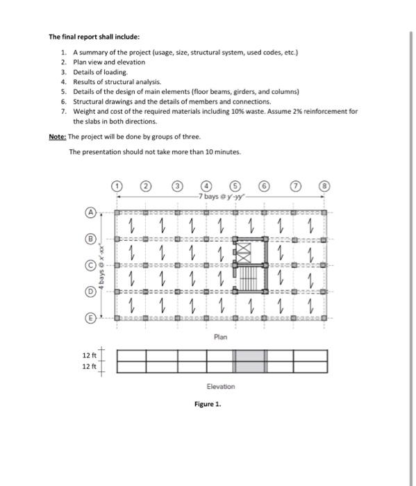
The final report shall include: 1. A summary of the project (usage, size, structural system, used codes, etc.) 2. Plan view and elevation 3. Details of loading. 4. Results of structural analysis. 5. Details of the design of main elements (floor beams, girders, and columns) 6. Structural drawings and the details of members and connections. 7. Weight and cost of the required materials including 10% waste. Assume 2% reinforcement for the slabs in both directions. Note: The project will be done by groups of three. The presentation should not take more than 10 minutes. 1 -7 bays @y-yy 1 1 1 1 12 ft 12 ft 4 bays@xxx +++ 1 1 1 1 Plan Elevation Figure 1. X1 1 1 1 1