Page 1 of 1
Design of Continuously Supported Beam A simply-supported beam with an overhang is subjected to a superimposed dead load
Posted: Thu May 05, 2022 11:44 am
by answerhappygod
- Design Of Continuously Supported Beam A Simply Supported Beam With An Overhang Is Subjected To A Superimposed Dead Load 1 (148.95 KiB) Viewed 47 times
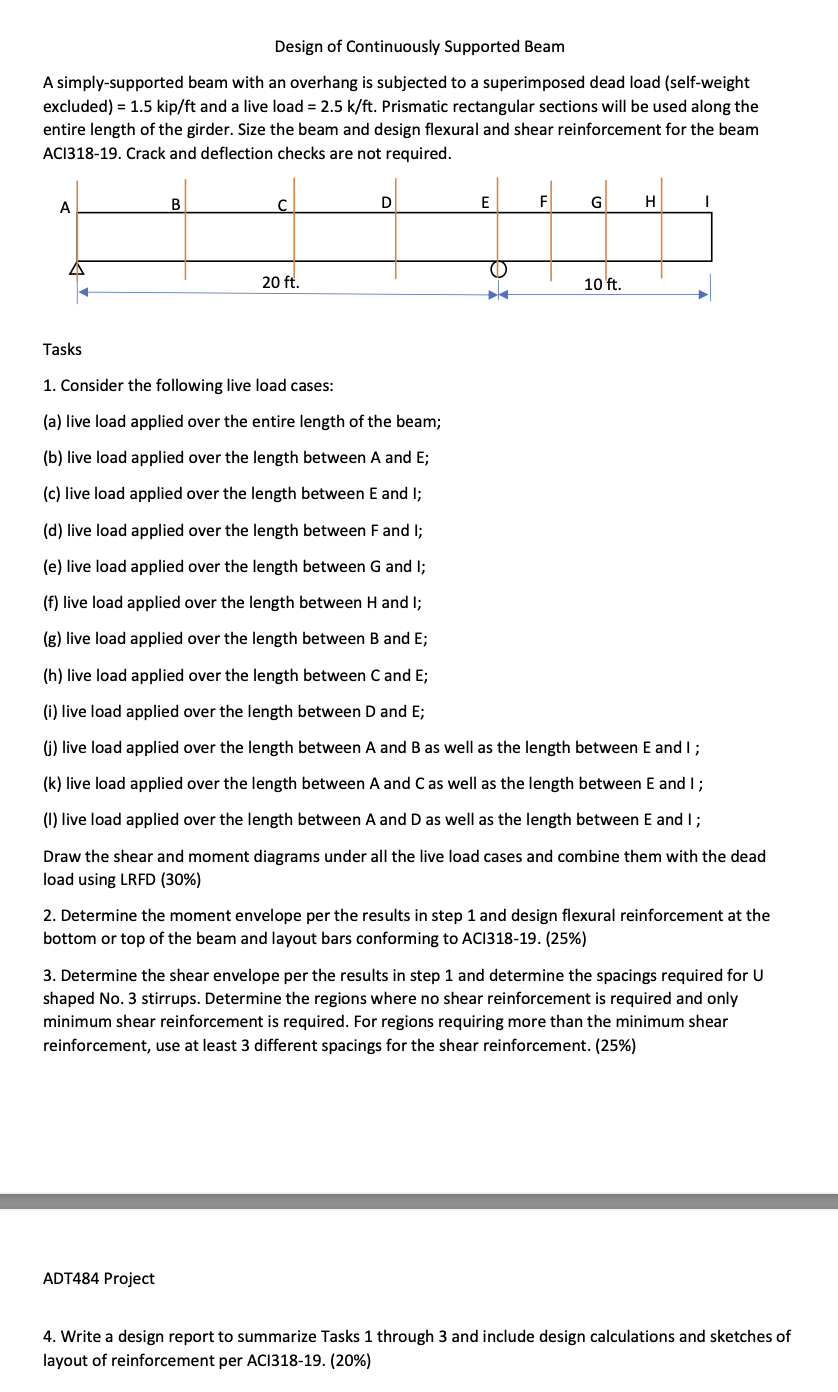
Design of Continuously Supported Beam A simply-supported beam with an overhang is subjected to a superimposed dead load (self-weight excluded) = 1.5 kip/ft and a live load = 2.5 k/ft. Prismatic rectangular sections will be used along the entire length of the girder. Size the beam and design flexural and shear reinforcement for the beam ACI318-19. Crack and deflection checks are not required. B C D E F G A H I 20 ft. 10 ft. Tasks 1. Consider the following live load cases: (a) live load applied over the entire length of the beam; (b) live load applied over the length between A and E; (c) live load applied over the length between E and I; (d) live load applied over the length between F and I; (e) live load applied over the length between G and I; (f) live load applied over the length between H and I; (g) live load applied over the length between B and E; (h) live load applied over the length between C and E; (i) live load applied over the length between D and E; (j) live load applied over the length between A and B as well as the length between E and I ; (k) live load applied over the length between A and C as well as the length between E and I ; (1) live load applied over the length between A and D as well as the length between E and I ; Draw the shear and moment diagrams under all the live load cases and combine them with the dead load using LRFD (30%) 2. Determine the moment envelope per the results in step 1 and design flexural reinforcement at the bottom or top of the beam and layout bars conforming to ACI318-19. (25%) 3. Determine the shear envelope per the results in step 1 and determine the spacings required for U shaped No. 3 stirrups. Determine the regions where no shear reinforcement is required and only minimum shear reinforcement is required. For regions requiring more than the minimum shear reinforcement, use at least 3 different spacings for the shear reinforcement. (25%) ADT484 Project 4. Write a design report to summarize Tasks 1 through 3 and include design calculations and sketches of layout of reinforcement per ACI318-19. (20%)