Page 1 of 1
16(a) The diagram below (Figure 9) shows an experimental setup of Faraday effect. Two polarisers are inserted in the opt
Posted: Wed May 04, 2022 1:32 pm
by answerhappygod
- 16 A The Diagram Below Figure 9 Shows An Experimental Setup Of Faraday Effect Two Polarisers Are Inserted In The Opt 1 (86.4 KiB) Viewed 63 times
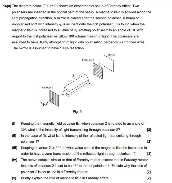
16(a) The diagram below (Figure 9) shows an experimental setup of Faraday effect. Two polarisers are inserted in the optical path of the setup. A magnetic field is applied along the light propagation direction. A mirror is placed after the second polariser. A beam of unpolarised light with intensity I, is incident onto the first polariser. It is found when the magnetic field is increased to a value of Bo, rotating polariser 2 to an angle of 10° with regard to the first polariser will allow 100% transmission of light. The polarisers are assumed to have 100% absorption of light with polarisation perpendicular to their axes. The mirror is assumed to have 100% reflection. Mirror Polariser 2 Polariser 1 Fig. 9 (i) Keeping the magnetic field at value Bo, when polariser 2 is rotated to an angle of 30°, what is the intensity of light transmitting through polariser 2? [2] (ii) In the case of (i), what is the intensity of the reflected light transmitting through polariser 1? [2] (iii) Keeping polariser 2 at 30°, to what value should the magnetic field be increased in order to have a zero transmission of the reflected light through polariser 1? [2] (iv) The above setup is similar to that of Faraday rotator, except that in Faraday rotator the axis of polariser 2 is set to be 45° to that of polariser 1. Explain why the axis of polariser 2 is set to 45° in a Faraday rotator. [2] (v) Briefly explain the role of magnetic field in Faraday effect. [2] ** B b