Page 1 of 1
2. b) Draw the bending moment, shear force, axial force diagrams and deflected shape for the frame shown below, showing
Posted: Wed May 04, 2022 9:08 am
by answerhappygod
- 2 B Draw The Bending Moment Shear Force Axial Force Diagrams And Deflected Shape For The Frame Shown Below Showing 1 (35.76 KiB) Viewed 35 times
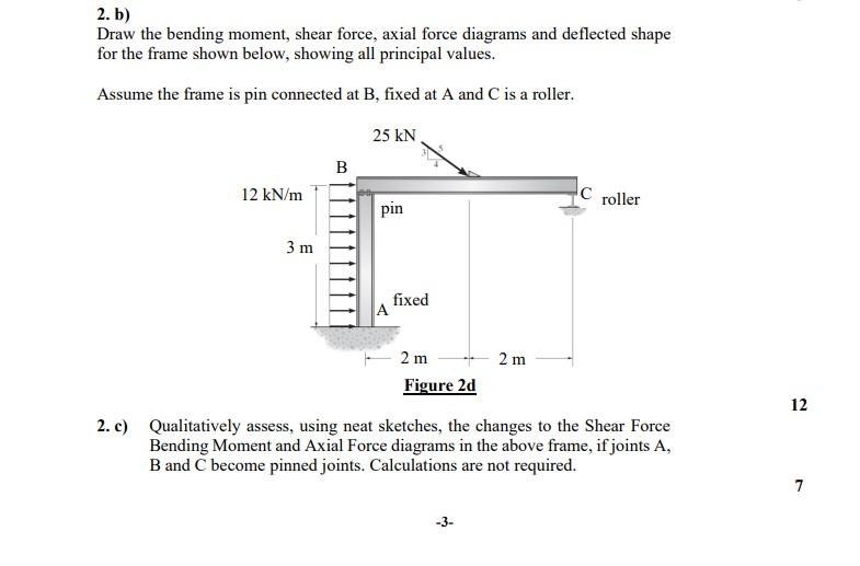
2. b) Draw the bending moment, shear force, axial force diagrams and deflected shape for the frame shown below, showing all principal values. Assume the frame is pin connected at B, fixed at A and C is a roller. 25 KN B 12 kN/m C roller pin 3 m fixed 2m 2 m Figure 2d 2. c) Qualitatively assess, using neat sketches, the changes to the Shear Force Bending Moment and Axial Force diagrams in the above frame, if joints A, B and C become pinned joints. Calculations are not required. -3- A 12 7