Page 1 of 1
(3) (a) For the system shown on the next page, you need to find hp vs Q for the system and, using the pump curve, find t
Posted: Wed May 04, 2022 9:08 am
by answerhappygod
- 3 A For The System Shown On The Next Page You Need To Find Hp Vs Q For The System And Using The Pump Curve Find T 1 (229.51 KiB) Viewed 33 times
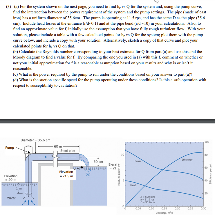
(3) (a) For the system shown on the next page, you need to find hp vs Q for the system and, using the pump curve, find the intersection between the power requirement of the system and the pump settings. The pipe (made of cast iron) has a uniform diameter of 35.6cm. The pump is operating at 11.5 rps, and has the same D as the pipe (35.6 cm). Include head losses at the entrance (r/d-0.1) and at the pipe bend (r/d-10) in your calculations. Also, to find an approximate value for f, initially use the assumption that you have fully rough turbulent flow. With your solution, please include a table with a few calculated points for hp vs Q for the system; plot them with the pump curve below, and include a copy with your solution. Alternatively, sketch a copy of that curve and plot your calculated points for hp vs Q on that. (b) Calculate the Reynolds number corresponding to your best estimate for Q from part (a) and use this and the Moody diagram to find a value for f. By comparing the one you used in (a) with this f, comment on whether or not your initial approximation for f' is a reasonable assumption based on your results and why is or isn't it reasonable. (c) What is the power required by the pump to run under the conditions based on your answer to part (a)? (d) What is the suction specific speed for the pump operating under these conditions? Is this a safe operation with respect to susceptibility to cavitation? Diameter 35.6 cm 100 10 80 60 Pump Elevation. = 20 m Water 1 m ^^ 60 m Steel pipe Elevation = 21.5 m BELL 50 cm Eleva = 21 Head, m; power, kW 0 Power Head N=690 rpm = 11.5 rps D = 35.6 cm 0.10 0.05 0.15 Discharge, m³/s 0.20 Efficiency 0.25 20 0.30 Efficiency, percent