Page 1 of 1
3. (a) Figure 3(a) shows a frame subjected to a concentrated moment of M kNm about point B and a linearly varying distri
Posted: Wed May 04, 2022 8:56 am
by answerhappygod
- 3 A Figure 3 A Shows A Frame Subjected To A Concentrated Moment Of M Knm About Point B And A Linearly Varying Distri 1 (39.79 KiB) Viewed 33 times
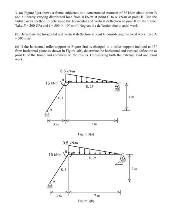
3. (a) Figure 3(a) shows a frame subjected to a concentrated moment of M kNm about point B and a linearly varying distributed load from 0 kN/m at point C to w kN/m at point B. Use the virtual work method to determine the horizontal and vertical deflection at joint B of the frame. Take E = 200 GPa and I= 500 x 10 mm. Neglect the deflection due to axial work. (b) Determine the horizontal and vertical deflection at joint B considering the axial work. Use A = 500 mm². (c) If the horizontal roller support in Figure 3(a) is changed to a roller support inclined at 15⁰ from horizontal plane as shown in Figure 3(b), determine the horizontal and vertical deflection at joint B of the frame and comment on the results. Considering both the external load and axial work. 3.5 kN/m 15 kNm E, 2/ 1 E, I 3 m 15 kNm A E, I 3 m 3.5 kN/m 7m Figure 3(a) E. 21 7m Figure 3(b) KB 4 m 4 m