Page 1 of 1
(A4) Figure A4 shows a rotor assembly with out-of-balance masses in planes B and C. The MRD products for the masses are
Posted: Mon May 02, 2022 5:04 pm
by answerhappygod
- A4 Figure A4 Shows A Rotor Assembly With Out Of Balance Masses In Planes B And C The Mrd Products For The Masses Are 1 (266.46 KiB) Viewed 49 times
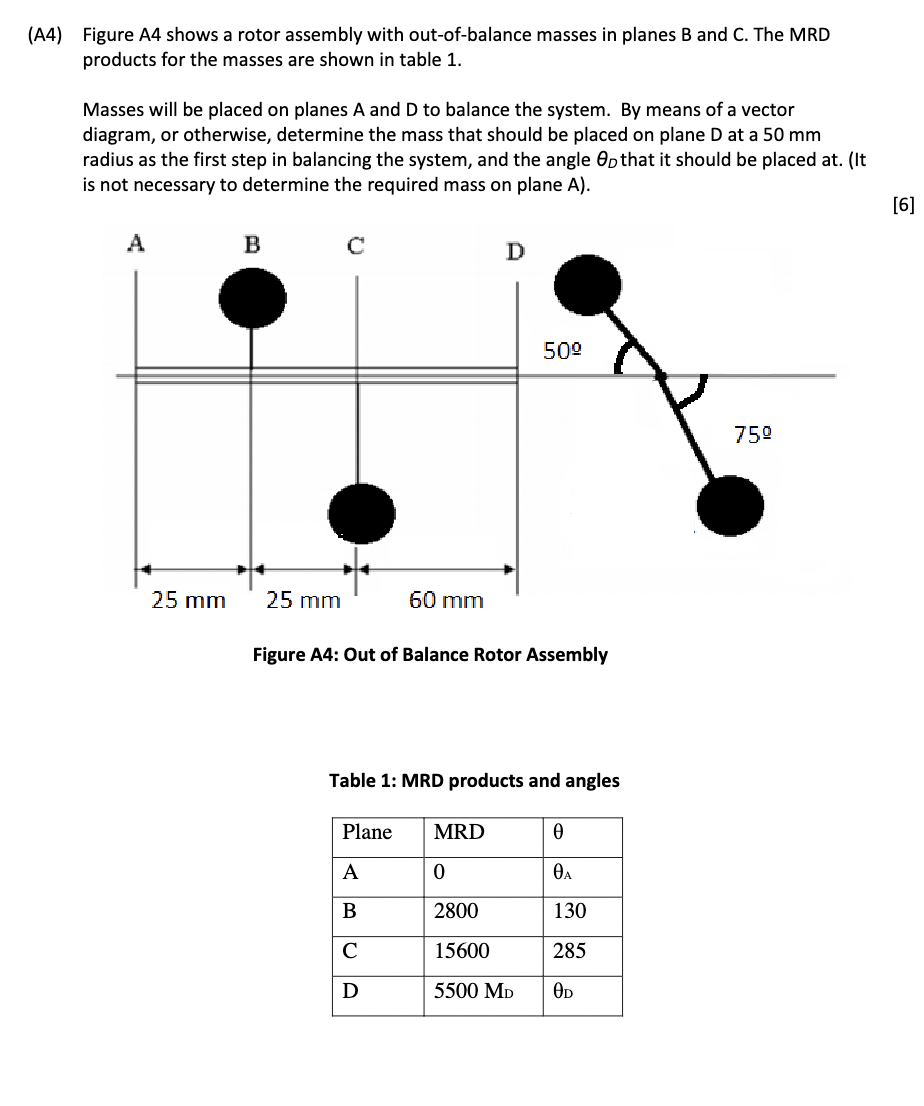
(A4) Figure A4 shows a rotor assembly with out-of-balance masses in planes B and C. The MRD products for the masses are shown in table 1. Masses will be placed on planes A and D to balance the system. By means of a vector diagram, or otherwise, determine the mass that should be placed on plane D at a 50 mm radius as the first step in balancing the system, and the angle Opthat it should be placed at. (It is not necessary to determine the required mass on plane A). [6] A B с D 75⁰ 25 mm 50⁰ 25 mm 60 mm Figure A4: Out of Balance Rotor Assembly Table 1: MRD products and angles Plane MRD 0 A 0 0A B 2800 130 C 15600 285 D 5500 MD OD