Page 1 of 1
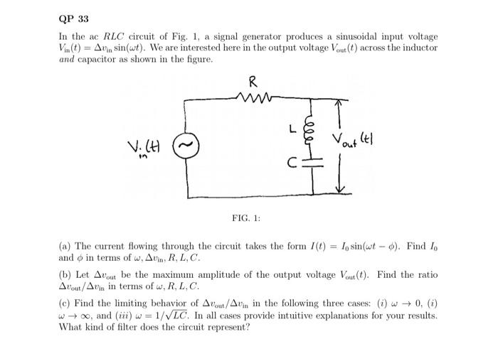
QP 33 In the ac RLC circuit of Fig. 1, a signal generator produces a sinusoidal input voltage Vin(t) = Avin sin(wt). We
Posted: Mon May 02, 2022 4:45 pm
by answerhappygod
- Qp 33 In The Ac Rlc Circuit Of Fig 1 A Signal Generator Produces A Sinusoidal Input Voltage Vin T Avin Sin Wt We 1 (31.78 KiB) Viewed 28 times
QP 33 In the ac RLC circuit of Fig. 1, a signal generator produces a sinusoidal input voltage Vin(t) = Avin sin(wt). We are interested here in the output voltage Vout(t) across the inductor and capacitor as shown in the figure. R ler VICH Vout it! 뙤 FIG. 1: (a) The current flowing through the circuit takes the form (t) = 1, sin(wt - ). Find I, and o in terms of w, Avin, R,L,C. (b) Let Arout be the maximum amplitude of the output voltage Vout(t). Find the ratio About/Aun in terms of W.R.L.C. (e) Find the limiting behavior of Avent/Avin in the following three cases: (i) w +0. (1) w+, and (ii) w = 1/VLC. In all cases provide intuitive explanations for your results. What kind of filter does the circuit represent?