Page 1 of 1
3. Consider the beam shown in Fig Q3. 1 = 5 m; F = 50 kN (a) There is a choice of beams with the following values for fl
Posted: Mon May 02, 2022 3:53 pm
by answerhappygod
- 3 Consider The Beam Shown In Fig Q3 1 5 M F 50 Kn A There Is A Choice Of Beams With The Following Values For Fl 1 (116.34 KiB) Viewed 18 times
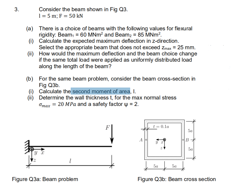
3. Consider the beam shown in Fig Q3. 1 = 5 m; F = 50 kN (a) There is a choice of beams with the following values for flexural rigidity: Beam1 = 60 MNm? and Beam2 = 85 MNm?. (i) Calculate the expected maximum deflection in Z-direction. Select the appropriate beam that does not exceed Zmax = 25 mm. (ii) How would the maximum deflection and the beam choice change if the same total load were applied as uniformly distributed load along the length of the beam? (b) For the same beam problem, consider the beam cross-section in Fig Q3b. (i) Calculate the second moment of area, I. (ii) Determine the wall thickness t, for the max normal stress Omax = 20 MPa and a safety factor y = 2. t = 0.1a 5a А B* ух 5a ут 1 t 5а + 5a + Figure Q3a: Beam problem Figure Q3b: Beam cross section