Page 1 of 1
Q3. FM (40 marks) Build a Simulink model following Figure 3. FM Sine Wave Function FM Modulator Passband Spectrum Analyz
Posted: Mon May 02, 2022 2:38 pm
by answerhappygod
- Q3 Fm 40 Marks Build A Simulink Model Following Figure 3 Fm Sine Wave Function Fm Modulator Passband Spectrum Analyz 1 (46.21 KiB) Viewed 45 times
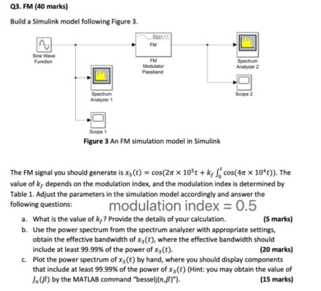
Q3. FM (40 marks) Build a Simulink model following Figure 3. FM Sine Wave Function FM Modulator Passband Spectrum Analyzer 2 Spectrum Analyzer Scope 2 Scope 1 Figure 3 An FM simulation model in Simulink The FM signal you should generate is xz(t) = cos(21 x 105t + kr Scos(41 x 10*t)). The value of k, depends on the modulation index, and the modulation index is determined by Table 1. Adjust the parameters in the simulation model accordingly and answer the following questions: modulation index = 0.5 a. What is the value of kp? Provide the details of your calculation. (5 marks) b. Use the power spectrum from the spectrum analyzer with appropriate settings, obtain the effective bandwidth of xz(t), where the effective bandwidth should include at least 99.99% of the power of xj(t). (20 marks) c. Plot the power spectrum of xz(t) by hand, where you should display components that include at least 99.99% of the power of xz(t) (Hint: you may obtain the value of In() by the MATLAB command "besseljin.BY"). (15 marks)