Page 1 of 1
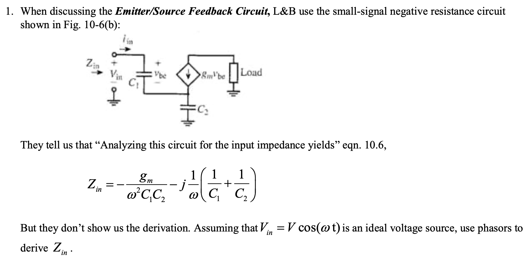
1. When discussing the Emitter/Source Feedback Circuit, L&B use the small-signal negative resistance circuit shown in Fi
Posted: Mon May 02, 2022 2:24 pm
by answerhappygod
- 1 When Discussing The Emitter Source Feedback Circuit L B Use The Small Signal Negative Resistance Circuit Shown In Fi 1 (139.06 KiB) Viewed 41 times
1. When discussing the Emitter/Source Feedback Circuit, L&B use the small-signal negative resistance circuit shown in Fig. 10-6(b): be &.be Load 1 C They tell us that "Analyzing this circuit for the input impedance yields” eqn. 10.6, 8m 1 1 1 Z j ਕੇ ਵੀ (6) + in oʻcc, C But they don't show us the derivation. Assuming that Vin = V cos(@t) is an ideal voltage source, use phasors to = derive Zin