Page 1 of 1
Part of a power system is illustrated in the figure below. Three synchronous generators are connected in parallel to the
Posted: Mon May 02, 2022 1:20 pm
by answerhappygod
- Part Of A Power System Is Illustrated In The Figure Below Three Synchronous Generators Are Connected In Parallel To The 1 (79.45 KiB) Viewed 25 times
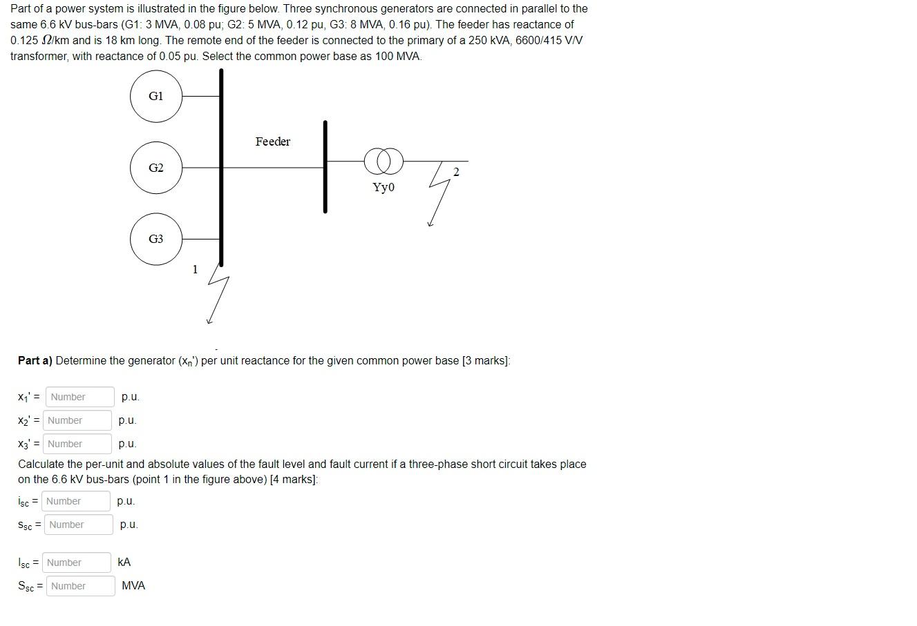
Part of a power system is illustrated in the figure below. Three synchronous generators are connected in parallel to the same 6.6 kV bus-bars (G1: 3 MVA, 0.08 pu; G2: 5 MVA, 0.12 pu, G3: 8 MVA, 0.16 pu). The feeder has reactance of 0.125 2/km and is 18 km long. The remote end of the feeder is connected to the primary of a 250 kVA, 6600/415 VN transformer, with reactance of 0.05 pu. Select the common power base as 100 MVA. G1 Feeder G2 Үyo G3 Part a) Determine the generator (Xn") per unit reactance for the given common power base [3 marks) X1' = Number p.u. X2' = Number p.u. X3' = Number p.u. Calculate the per-unit and absolute values of the fault level and fault current if a three-phase short circuit takes place on the 6.6 kV bus-bars (point 1 in the figure above) [4 marks]: isc = Number p.u. Ssc = Number p.u. Isc = Number KA Ssc = Number MVA