Page 1 of 1
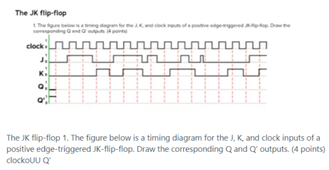
The JK flip-flop 1. The figure below is a timing diagram for the J, K, and clock inputs of a positive edge-triggered JK-
Posted: Mon May 02, 2022 1:20 pm
by answerhappygod
- The Jk Flip Flop 1 The Figure Below Is A Timing Diagram For The J K And Clock Inputs Of A Positive Edge Triggered Jk 1 (119.45 KiB) Viewed 29 times
The JK flip-flop 1. The figure below is a timing diagram for the J, K, and clock inputs of a positive edge-triggered JK-lip-flop.Draw the corresponding and outputs. (4 points) clock man J!! Ki ம The JK flip-flop 1. The figure below is a timing diagram for the J, K, and clock inputs of a positive edge-triggered JK-flip-flop. Draw the corresponding Q and Q' outputs. (4 points) clockouUQ