Page 1 of 1
1.2 Build the circuit given in Figure-2 which contains 2 capacitors connected in series. Initially disconnect the power
Posted: Mon May 02, 2022 1:19 pm
by answerhappygod
- 1 2 Build The Circuit Given In Figure 2 Which Contains 2 Capacitors Connected In Series Initially Disconnect The Power 1 (56.56 KiB) Viewed 32 times
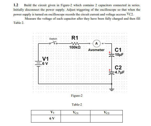
1.2 Build the circuit given in Figure-2 which contains 2 capacitors connected in series. Initially disconnect the power supply. Adjust triggering of the oscilloscope so that when the power supply is turned on oscilloscope records the circuit current and voltage accross Vc2. Measure the voltage of each capacitor after they have been fully charged and then fill Table 2. Switch R1 A w 100kΩ Avometer C1 10uF V1 26 V C2 -4.7uF Figure-2 Table-2 V1 Vci Vc2 6 V