Page 1 of 1
2.2 Now construct the following circuit given in Figure-4. Initially disconnect the power supply. Adjust triggering of t
Posted: Mon May 02, 2022 1:15 pm
by answerhappygod
- 2 2 Now Construct The Following Circuit Given In Figure 4 Initially Disconnect The Power Supply Adjust Triggering Of T 1 (62.88 KiB) Viewed 39 times
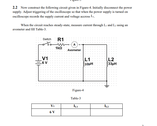
2.2 Now construct the following circuit given in Figure-4. Initially disconnect the power supply. Adjust triggering of the oscilloscope so that when the power supply is turned on oscilloscope records the supply current and voltage accross L. When the circuit reaches steady-state, measure current through L, and L2 using an avometer and fill Table-3. Switch R1 1kΩ Avometer V1 6 V L1 3100H L2 Ўззин Figure-4 Table-3 V1 ILI IL2 6 V