Page 1 of 1
2.1 Firstly, calculate the time constant of the circuit. Then, build the circuit given in Figure-4 below. Initially disc
Posted: Mon May 02, 2022 1:15 pm
by answerhappygod
- 2 1 Firstly Calculate The Time Constant Of The Circuit Then Build The Circuit Given In Figure 4 Below Initially Disc 1 (53.01 KiB) Viewed 43 times
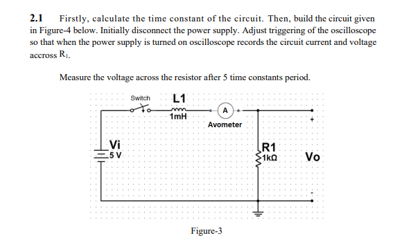
2.1 Firstly, calculate the time constant of the circuit. Then, build the circuit given in Figure-4 below. Initially disconnect the power supply. Adjust triggering of the oscilloscope so that when the power supply is turned on oscilloscope records the circuit current and voltage accross R. Measure the voltage across the resistor after 5 time constants period. L1 Switch 1mH Avometer Vi - 5 V R1 1kΩ Vo = Figure-3