Page 1 of 1
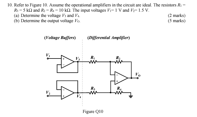
10. Refer to Figure 10. Assume the operational amplifiers in the circuit are ideal. The resistors R1 = R3 = 5 k12 and R2
Posted: Mon May 02, 2022 1:01 pm
by answerhappygod
- 10 Refer To Figure 10 Assume The Operational Amplifiers In The Circuit Are Ideal The Resistors R1 R3 5 K12 And R2 1 (30.65 KiB) Viewed 32 times
10. Refer to Figure 10. Assume the operational amplifiers in the circuit are ideal. The resistors R1 = R3 = 5 k12 and R2 = R4 = 10 k 2. The input voltages Vi=1 V and V2=1.5 V. (a) Determine the voltage V3 and V4. (2 marks) (b) Determine the output voltage Vo. (5 marks) (Voltage Buffers) (Differential Amplifier) R R2 V. R3 R4 V2 Figure Q10