Page 1 of 1
Question 2 The rod shown Figure 2 below is built in at ends a and d. An axial load of P is applied at point c as shown i
Posted: Mon May 02, 2022 11:30 am
by answerhappygod
- Question 2 The Rod Shown Figure 2 Below Is Built In At Ends A And D An Axial Load Of P Is Applied At Point C As Shown I 1 (43.19 KiB) Viewed 24 times
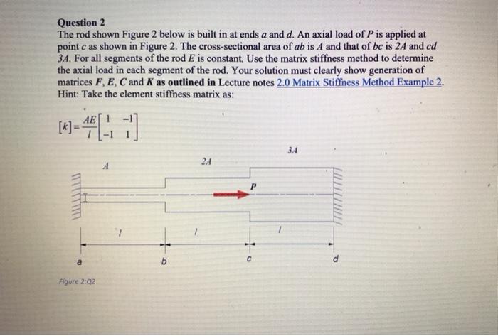
Question 2 The rod shown Figure 2 below is built in at ends a and d. An axial load of P is applied at point c as shown in Figure 2. The cross-sectional area of ab is A and that of bc is 24 and cd 34. For all segments of the rod E is constant. Use the matrix stiffness method to determine the axial load in each segment of the rod. Your solution must clearly show generation of matrices F, E, C and K as outlined in Lecture notes 2.0 Matrix Stiffness Method Example 2. Hint: Take the element stiffness matrix as: -41] 3A 2A Figure 2:02 C THE77777 P