Page 1 of 1
Q2. A bridge support has an l-shaped cross section as illustrated in Figure Q2, with a thickness of 15 mm along both the
Posted: Mon May 02, 2022 10:57 am
by answerhappygod
- Q2 A Bridge Support Has An L Shaped Cross Section As Illustrated In Figure Q2 With A Thickness Of 15 Mm Along Both The 1 (125.23 KiB) Viewed 33 times
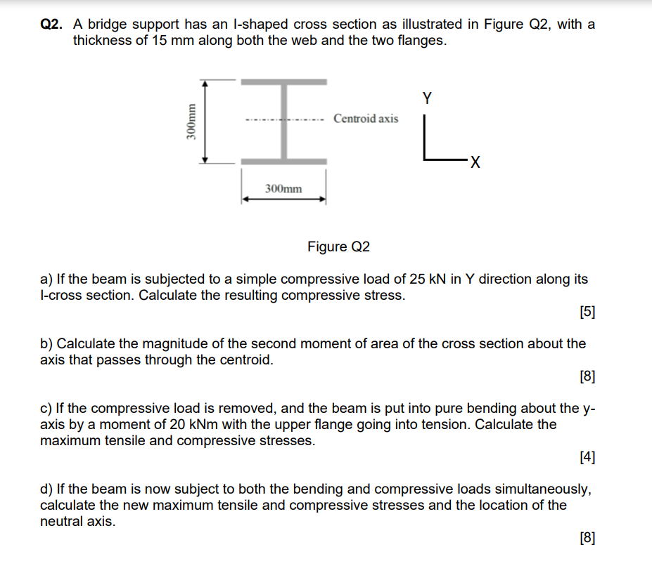
Q2. A bridge support has an l-shaped cross section as illustrated in Figure Q2, with a thickness of 15 mm along both the web and the two flanges. Y 300mm . Centroid axis -X 300mm Figure Q2 a) If the beam is subjected to a simple compressive load of 25 kN in Y direction along its l-cross section. Calculate the resulting compressive stress. [5] b) Calculate the magnitude of the second moment of area of the cross section about the axis that passes through the centroid. [8] c) If the compressive load is removed, and the beam is put into pure bending about the y- axis by a moment of 20 kNm with the upper flange going into tension. Calculate the maximum tensile and compressive stresses. [4] d) If the beam is now subject to both the bending and compressive loads simultaneously, calculate the new maximum tensile and compressive stresses and the location of the neutral axis. [8]