Page 1 of 1
SITUATION 2. The figure below is a C375 x 60. The holes are 22-mm in diameter. For route A-B and C-D, gage = 116.8 mm. T
Posted: Mon May 02, 2022 10:56 am
by answerhappygod
- Situation 2 The Figure Below Is A C375 X 60 The Holes Are 22 Mm In Diameter For Route A B And C D Gage 116 8 Mm T 1 (110.39 KiB) Viewed 61 times
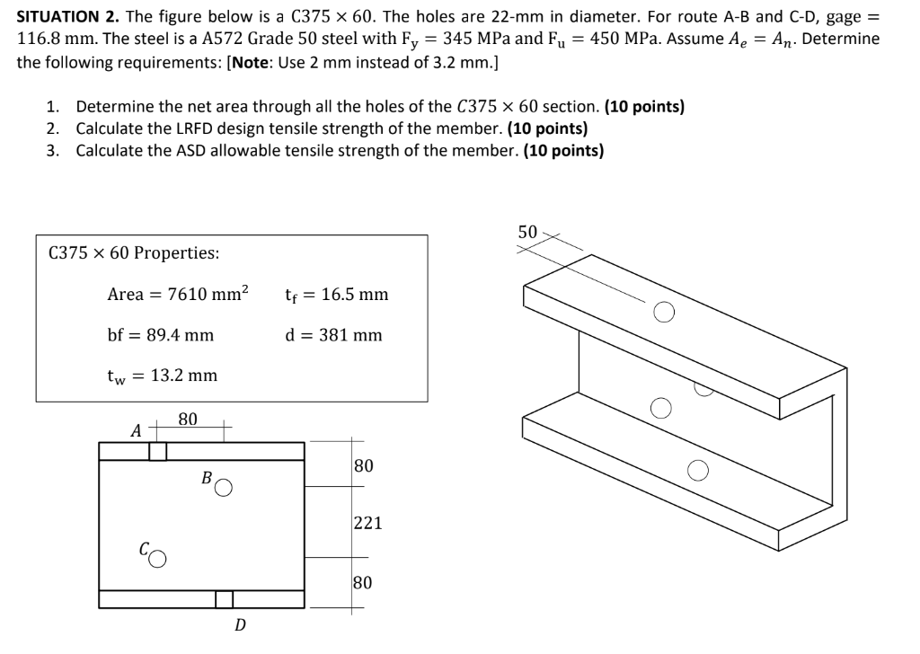
SITUATION 2. The figure below is a C375 x 60. The holes are 22-mm in diameter. For route A-B and C-D, gage = 116.8 mm. The steel is a A572 Grade 50 steel with Fy = 345 MPa and Fu = 450 MPa. Assume Ae = An. Determine the following requirements: (Note: Use 2 mm instead of 3.2 mm.) 1. Determine the net area through all the holes of the C375 x 60 section. (10 points) 2. Calculate the LRFD design tensile strength of the member. (10 points) 3. Calculate the ASD allowable tensile strength of the member. (10 points) 50 C375 x 60 Properties: Area = 7610 mm2 te = 16.5 mm bf = 89.4 mm d = 381 mm tw = 13.2 mm 80 А 80 B 221 80 D